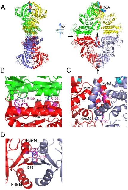
Figure 4. Structure of the mmNAGS/K tetramer and interfaces between subunits shown as ribbon diagrams.
A. The tetramer is shown in two different orientations, perpendicular to the plane of the ring, and parallel to the plane of the ring. Subunit A (red), subunit B (green), subunit X (purple -gray) and subunit Y (yellow). Bound CoA molecule is shown as a space-filling model. The two 2-fold non-crystallographic rotation axes in the plane of the ring are indicated by arrows and the 2-fold non-crystallographic rotation axis perpendicular to the plane of the ring is indicated by a filled oval. B. ecNAGK-like AAK-AAK domain interface between subunits A and B; α-helices, H5 and H6, and β-strands, B3 and B8, form this interface. C. N-terminal helix interface between subunits A and X, formed by interactions between the two N-terminal α-helices and two neighboring helices, H3 and H10. D. NAT-NAT domain interface between subunits A and X. Two α-helices, H14 and H15, and one β-strand, B18, form this interface.

