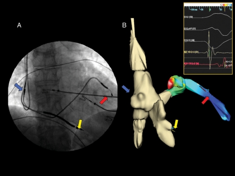
Figure 2.
(A) Final implantation of the cardiac resynchronization therapy–implantable cardioverter–defibrillator device in an antero-posterior projection and the arrows indicate the three-lead positions (blue arrow, right atrial lead; yellow arrow, right ventricular lead; and red arrow, left ventricular lead). (B) The same view of the final implantation of the cardiac resynchronization therapy–internal cardioverter-defibrillator device constructed using the NavX system. It is easy to appreciate how the two images correspond as regards the final position of the leads. The coronary sinus and the lateral vein in (B) also show the activation colour map of the left ventricle during sinus rhythm constructed using NavX system; the purple colour indicates the position of the maximum delay of ventricular activation and therefore the best final position for the left lead. The insert shows the electrograms of the right and left ventricle recorded by the leads during sinus rhythm.

