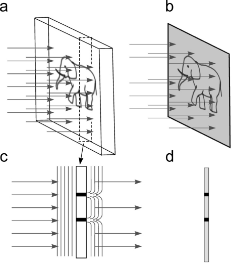
Figure 6.
Amplitude contrast. (a) An amplitude object illuminated by a parallel beam. (b) The image resulting from interaction of the beam with the sample. (c) A cross section of the object outlined by the dashed lines in (a); some of the rays are absorbed in the sample. Arrows show the changes in the wavefront after interaction with the sample. (d) Intensity of the rays creating the image in the region of the cross section. Black dots in the image correspond to areas of beam absorption (c).

