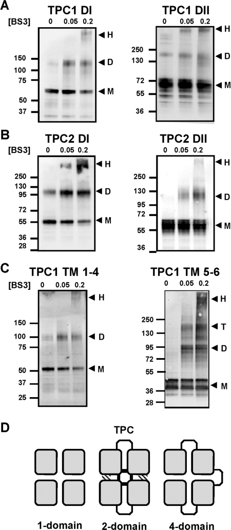
Figure 5. Cross-linking of TPCs.
(A–C) Western blot analysis of GFP-tagged hydrophobic domains of TPC1 (A), TPC2 (B) or the indicated TM regions of TPC1 (C). Experiments were performed in the presence of the indicated concentration (in mM) of BS3. The presence of monomeric (M), dimeric (D), tetrameric (T) or high-molecular-mass (H) products are highlighted by the arrows. The molecular mass in kDa is indicated on the left-hand side. (D) Schematic diagram showing the conservation of the four-domain (squares) architecture between tetrameric one-domain channels (e.g. Kv), dimeric two-domain channels (TPC) and monomeric four-domain channels (e.g. Cav). In TPCs, the central pore is likely to be formed by contacts between all four domains within the dimer (shaded regions), whereas regions outside the pore may form contacts with only one neighbouring domain (hatched regions).

