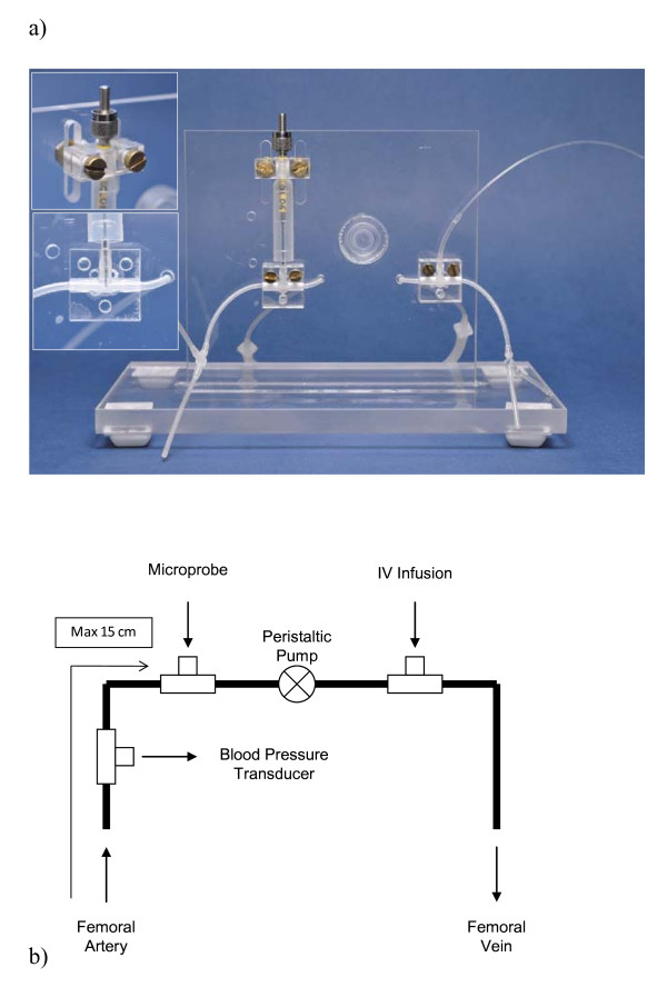
Figure 1.
The shunt apparatus. (a) The shunt apparatus mounted on the acrylic stand with adjustable clamps (upper probe mount and tip location inlaid); (b) Diagram illustrating the design of the shunt, with T-connections for blood pressure measurement, probe insertion, and intravenous infusion. The peristaltic pump is connected after the probe in series in order to prevent backflow from the IV infusion connection affecting probe measurements.

