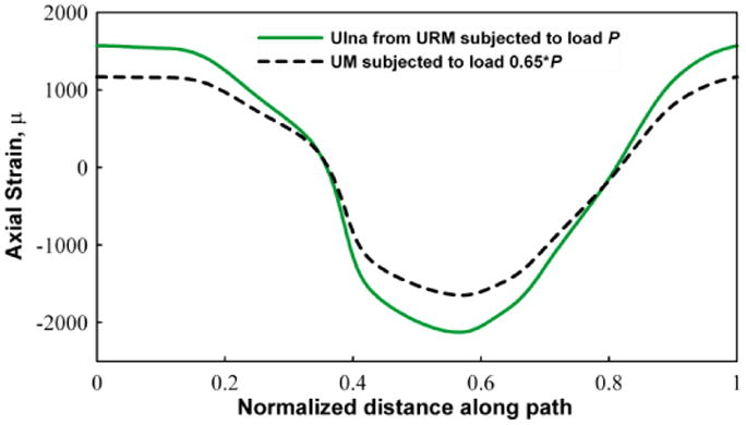
Figure 2.

Graph showing the variation of the z-direction strain (using 10 node fine mesh) around a circumferential path on the surface of ulna. The section is taken at the mid shaft region. The graph shows the comparison of the strain for the URM with a full 2 N load and the corresponding UM with 1.3 N (65%) load. Tensile and compressive strains are observed, as expected, in the medial and lateral sides of the ulna.
