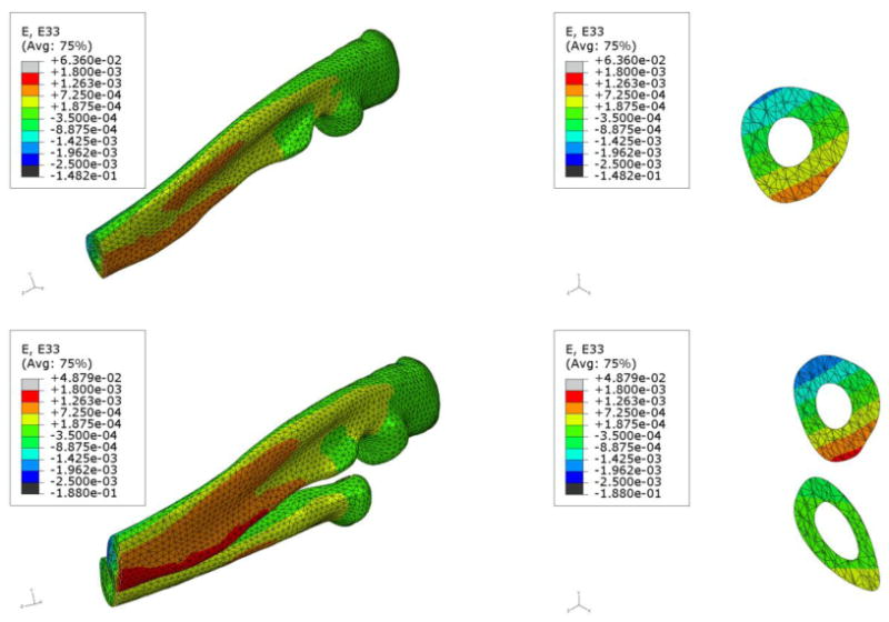
Figure 3.

Comparative images showing the z-direction strain contours (using 10 node fine mesh) on one half of the ulna in the UM (top) and the ulna and radius in the URM (bottom). The URM was subjected to 2 N axial force while the UM was subjected to 1.3 N axial force. From the images on the right hand side of each row, it can be clearly seen that the ulna in the URM experiences higher tensile stresses compared to the ulna in the UM.
