Abstract
Achieving superior outcomes through the use of robots in medical applications requires an integrated approach to the design of the robot, tooling and the procedure itself. In this paper, this approach is applied to develop a robotic technique for closing abnormal communication between the atria of the heart. The goal is to achieve the efficacy of surgical closure as performed on a stopped, open heart with the reduced risk and trauma of a beating-heart catheter-based procedure. In the proposed approach, a concentric tube robot is used to percutaneously access the right atrium and deploy a tissue approximation device. The device is constructed using a metal MEMS fabrication process and is designed to both fit the manipulation capabilities of the robot as well as to reproduce the beneficial features of surgical closure by suture. Experimental results demonstrate device efficacy through manual in-vivo deployment and bench-top robotic deployment.
I. Introduction
Existing surgical robots tend to mimic the techniques and tools used by surgeons in manual surgery. For example, robotic tools for minimally invasive surgery are often identical to the manual tools used to perform laparoscopic procedures, e.g., forceps, scissors, needles and suture [1],[2]. This approach can facilitate clinical adoption since it builds on the clinician’s existing skill set.
There are many surgeries, however, where the robotization of current techniques is either not feasible or does not produce improvements in outcome or efficiency. For robots to be effective in these situations, new surgical techniques and tools are needed to fit the capabilities of robots.
One such application is intracardiac surgery. While the demand for heart surgery is increasing, open-heart procedures that require stopping the heart are declining due to inherent clinical risks, creating opportunities for devices that can perform intracardiac procedures in a minimally invasive fashion on the beating heart. While catheters provide these capabilities for certain procedures, their inherent flexibility substantially limits their tip forces and positioning accuracy and so constrains the tools and procedures they can perform.
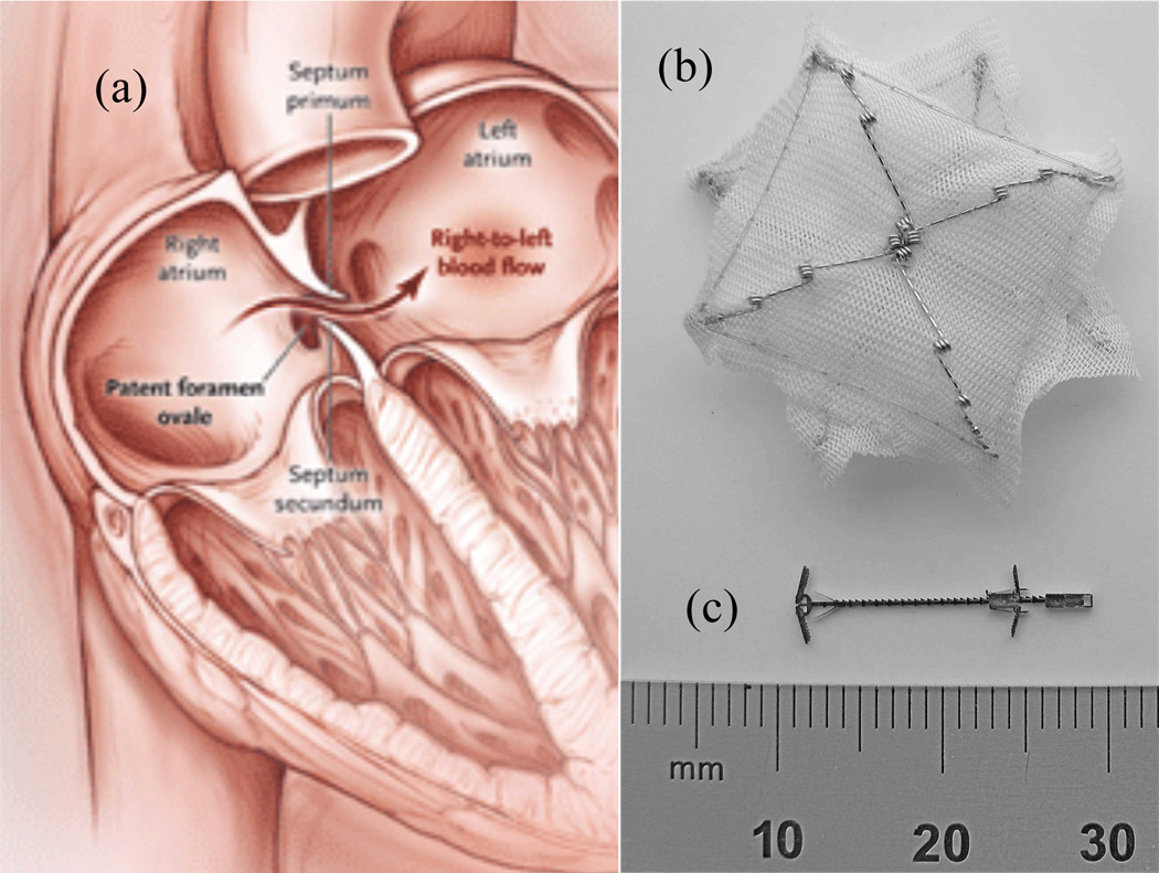
As a specific example, consider the closure of patent foramen ovales (PFO’s). Depicted in Fig. 1(a), the foramen ovale is an opening between the two atria of the heart that allows blood to circulate while bypassing the lungs prior to birth. It should close spontaneously shortly after birth but fails to close completely (is patent) in about 25% of the population. Many individuals with a PFO show no symptoms in their lifetime, but clots or particles in the blood in the right atrium that cross a PFO into the left atrium can cause strokes or heart attacks.
Fig. 1.
Patent foramen ovale (PFO) and closure devices. (a) PFO – blood returning from the body is shunted from the right to left atrium without first circulating to the lungs for filtration and oxygenation. (b) CardioSeal catheter-delivered occlusion device (c) Proposed metal MEMS tissue approximation device.
Surgical closure by suture is the gold standard of treatment. This approach is highly invasive and involves placing the patient on cardiopulmonary bypass and stopping the heart. Due to risks of open-heart surgery, this approach is rarely undertaken unless the patient is undergoing open-heart surgery for other reasons.
Alternatively, PFO’s can be closed using catheter-deployed occlusion devices inside the beating heart [3]. These devices are inserted through the PFO itself and act as a plug against blood flow. One such device (Cardioseal, NMT Medical), as shown in Fig 1(b), is double umbrella design that pops open when pushed out of a catheter. It is simple to deploy since the catheter need only pass through the existing PFO channel and push out an umbrella on each side of the hole. This is in contrast to closure by suture, which involves applying forces to pierce tissue and dexterous manipulation of needle and suture.
Closure using catheter-delivered occlusion devices is achieved in more than 90% of the cases; however, this approach has several disadvantages. First, a significant amount of foreign material is placed inside the left atrium leading to the possibility of thrombus formation and embolization. Second, unlike closure by suture, the devices are not adjustable. The force continuously exerted against the tissue can be excessive leading to tissue perforation and/or the device breaking free and becoming lodged in a valve.
The ideal PFO closure device would be delivered percutaneously, like catheter-delivered devices, but also provide adjustability, reliability and introduce the minimum possible amount of foreign material – as is obtained in suture closure. There are several challenges to satisfying these requirements. First, there is very little room in the right atrium to perform complex manipulations. Secondly, despite recent advances in robotic catheter systems [4]–[8], the dexterity, stiffness and positioning accuracy necessary to mimic suturing appear incompatible to catheter delivery.
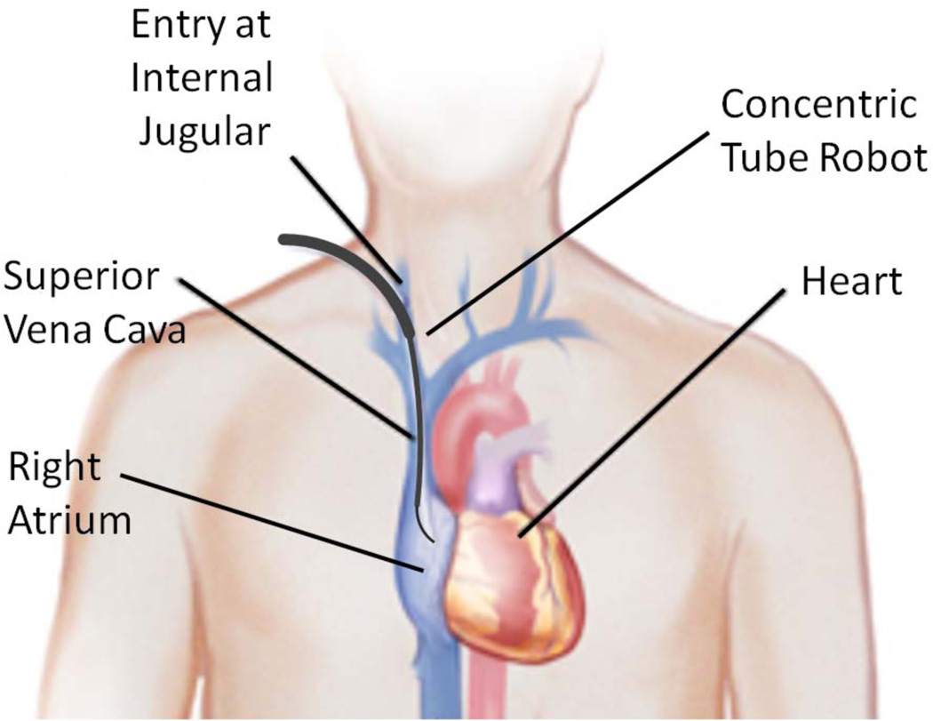
The contribution of this paper is to propose a solution comprised of a robotic delivery platform and a tissue approximation device designed to fit the capabilities of the robotic platform. The delivery platform, as illustrated in Fig. 2, is a concentric tube robot that is used for percutaneous access to the right atrium via the internal jugular vein in the neck. Substantially stiffer than a catheter, the robot can apply higher forces to manipulate tissue inside the heart. Concentric tube robots are a novel class of continuum robots comprised of nested pre-curved elastic tubes that are well suited to minimally invasive surgery [9]–[14].
Fig. 2.
Concentric tube robot entering the beating heart via the internal jugular vein.
The tissue approximation device (Fig. 1(c)) takes advantage of the robot’s force capabilities to adjustably approximate the two tissue layers (septum primum and septum secundum of Fig. 1(a)) in a manner comparable to suturing while not requiring the complex manipulations involved in throwing stitches and tying knots. Since the portion of the device protruding from the tissue is comparable in size to the suture used in surgical closure, it would be rapidly encapsulated in the tissue and would not carry the risks of the existing occlusion devices (compare Figs. 1(b) and 1(c)).
The paper is arranged as follows. The next section describes the metal MEMS process used to manufacture the tissue approximation device. Section III details the design of the approximation device and the procedure to deploy it. Section IV describes manual and robot deployment experiments used to evaluate the device. Conclusions appear in the final section of the paper.
II. Metal MEMS Device Fabrication
Currently, millimeter-scale surgical instruments and implants are produced in metal by methods such as numerically controlled machining, electrical discharge machining, grinding, and laser machining (e.g., for stents). In some cases, welding and forming methods may also be used, and for some components (if not too small), metal injection molding may be suitable.
These methods suffer from one or more constraints. These include the inability to make extremely small features (e.g., due to material deflection, inability to fixture/hold the workpiece) and the difficulty in making internal features (due to restricted tool access). In addition, device components are manufactured serially by these methods and often must be subsequently manually assembled under a microscope – resulting in high manufacturing costs.
In contrast, the metal MEMS technology used here (Microfabrica, Inc.) is an additive, freeform metal manufacturing process for volume manufacturing of micro- and millimeter-scale devices. Based on a 3D CAD model of the desired device, the process stacks independently-formed and patterned metal layers. The technology allows designers to create intricate 3D geometries with micron-level precision. It is a batch, wafer-scale process in which many devices are built simultaneously, allowing volume production at low cost.
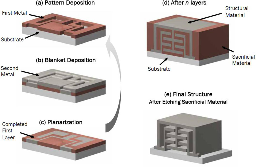
As illustrated in Fig. 3, the fabrication process utilizes a structural metal and a sacrificial metal. The structural metal is typically a nickel-cobalt alloy while the sacrificial metal is copper. Nickel cobalt has sufficient biocompatibility for use in surgical tools. For implants, however, long-term biocompatibility is required. Palladium (Pd) satisfies this requirement and is compatible with the fabrication process.
Fig. 3.
Metal MEMS fabrication process. The formation of each layer involves three steps: (a) Pattern deposition of a sacrificial metal, (b) blanket deposition of structural metal, and (c) planarization. After all layers are formed, the sacrificial metal is removed, leaving behind the assembled 3D device.
As a technology for millimeter-scale surgical devices, this process offers the following advantages. First, it permits the use of macro-scale mechanisms (e.g., hinges, slides, ratchets, chains, and pulleys) at the millimeter scale. This enables device designs with patient-to-patient adjustability through the use of ratcheting or other mechanisms resulting in much finer control over the forces exerted on tissue. Secondly, it is economical since hundreds or thousands of pre-assembled devices can be manufactured in a single batch. Thirdly, the fabrication process enables designs possessing superior material properties since it permits the use of combinations of structural metals, e.g., for high strength, hardness and biocompatibility.
III. Device Design
The catheter motions to install occlusion devices, such as the one shown in Fig. 1(b), consist of steering the soft catheter tip through the PFO channel so that it enters the left atrium. The distal patch of the occlusion device is pushed from the end of catheter and its nitinol struts spring open so that the patch completely covers the septal channel. After pulling the patch against the septum, the proximal patch is similarly deployed on the proximal side in the right atrium and the device is released. The nitinol struts press both patches against the septum with a force that depends on the thickness of the patient’s septal tissue.
In contrast to a catheter, a concentric tube robot possesses substantially higher longitudinal and bending stiffnesses as well as high precision control of tip position. These qualities enable precise puncture and manipulation of the septal tissue and so provide more design freedom for a robot-delivered device. The right atrium is a confined space (several centimeters in diameter), however, providing little room for the robot to perform complex manipulations. Thus, the delivery procedure should require simple robot motions.
In the proposed procedure, instead of covering the hole with foreign material, the robot punctures the two tissue layers forming the channel (septum primum and secundum in Fig. 1(a)) and the device, similar to suture closure, pulls them together just enough to seal the hole. The high axial and bending stiffnesses of the robot enable tissue puncture despite robot curvature. Furthermore, if the tissue layers do not overlap, the robot’s high lateral stiffness enables it to pull the septum secundum over the septum primum.
The device design specifications can be grouped as surgical requirements and robot delivery requirements.
Surgical requirements:
-
1
The distance that the tissue is approximated should be adjustable on a patient-specific basis.
-
2
The force required to separate the approximated tissues should be comparable to suture closure (1 N).
-
3
Any foreign material introduced into the heart should be as small as possible and not protrude into the left atrium.
Robot deployment requirements:
-
4
The device must be compliant in bending so that it can be delivered through the curves of the concentric tube robot.
-
5
Device deployment must be reliable and allow for removal of the device mid-deployment.
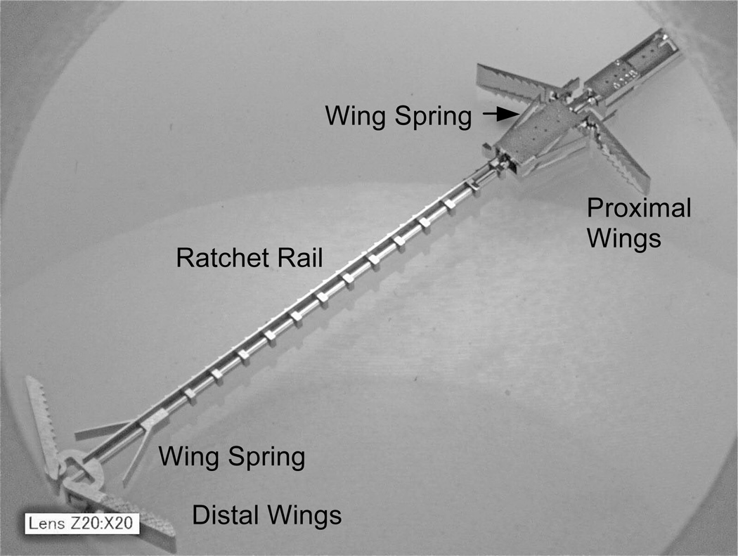
An enlarged view of the final device is shown in Fig. 4. Its cross section is 1.5 mm at its widest and it is 18 mm long. It has two pairs of expanding spring-loaded wings that are used to pull the tissue layers together. The distal wings attach to a toothed rail while the proximal wings are attached to a pawl flexure that engages the rail teeth forming a ratcheting mechanism, which adjusts the device length.
Fig. 4.
Tissue approximation device. Wings expand to push against tissue. Ratcheting mechanism enables clinician to adjust distance between wing pairs.
The delivery system consists of a tube and wire (not shown) at the proximal end of the device. The delivery wire screws into the device while the delivery tube mates with the device through a dog clutch.
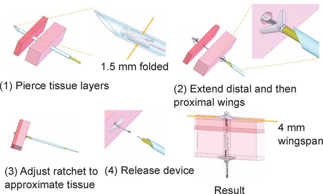
Device deployment is illustrated schematically in Fig. 5. The two tissue layers are first pierced at the location where approximation is desired. For manual deployment, as described later in the paper, a bevel-tipped cannula was used as shown for piercing the tissue. During robotic deployment, a sharpened stylet inserted through the robot was used in place of the cannula.
Fig. 5.
Tissue approximation device deployment sequence.
In the second step, the deployment tube and wire are both extended to push the device out of the robot tip. Flexure springs cause the wings to rotate by 30 degrees as they are extended from the robot to ensure that they will catch against the tissue. In the third step, relative translation of the deployment tube and wire causes the ratchet rail to shorten, pulling the tissue layers together while fully extending the wings. Finally, in step 4, counterclockwise rotation of the deployment wire with respect to the deployment tube releases the device. Alternately, if the deployment is unsatisfactory, the distal wings can be released and the device removed by clockwise rotation.
In summary, the device employs three degrees of freedom during deployment. The first is rigid-body translation along the axis of the delivery device. The second degree of freedom is for the ratcheting to bring the tissue together. It is produced by relative translation of the deployment tube and wire. The third degree of freedom is relative rotation between the tube and wire to release the device.
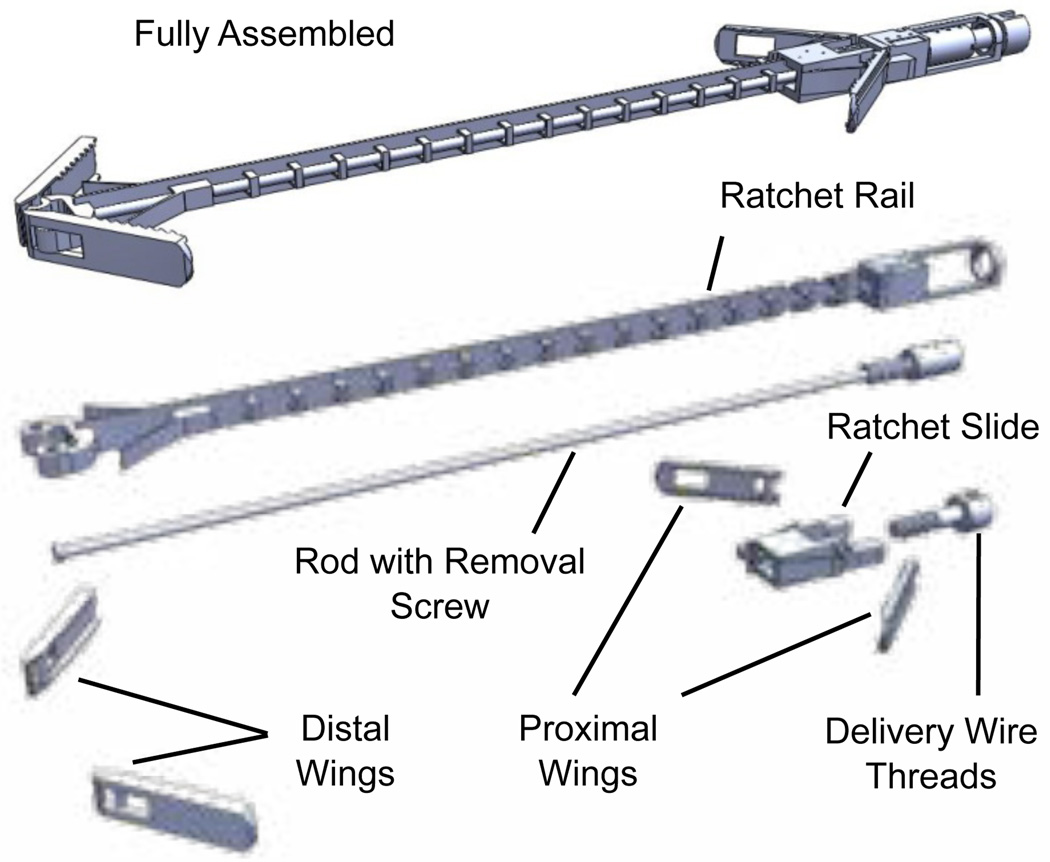
Hundreds of the approximation devices are fabricated fully assembled on a single wafer using the metal MEMS process described in the preceding section. As shown in Fig. 6, the device is comprised of eight moving parts. Details of the design process are provided in the following subsections.
Fig. 6.
Tissue approximation device with expanded view of all components.
A. Device Removal
During deployment, it is important to be able to remove a device from the patient. Reasons include inadequate positioning of the device, malfunction, as well as changes in the condition of the patient. This feature is incorporated in the approximation device design.
To remove the device safely, it must be retracted into the robot without tearing any tissue that it has passed through and without any parts breaking off to be carried away by the blood stream. Functionally, this requires that the proximal and distal wings fold against the body of the device. The proximal wings will pivot in the correct direction during retraction. This is not true of the distal wings, however.
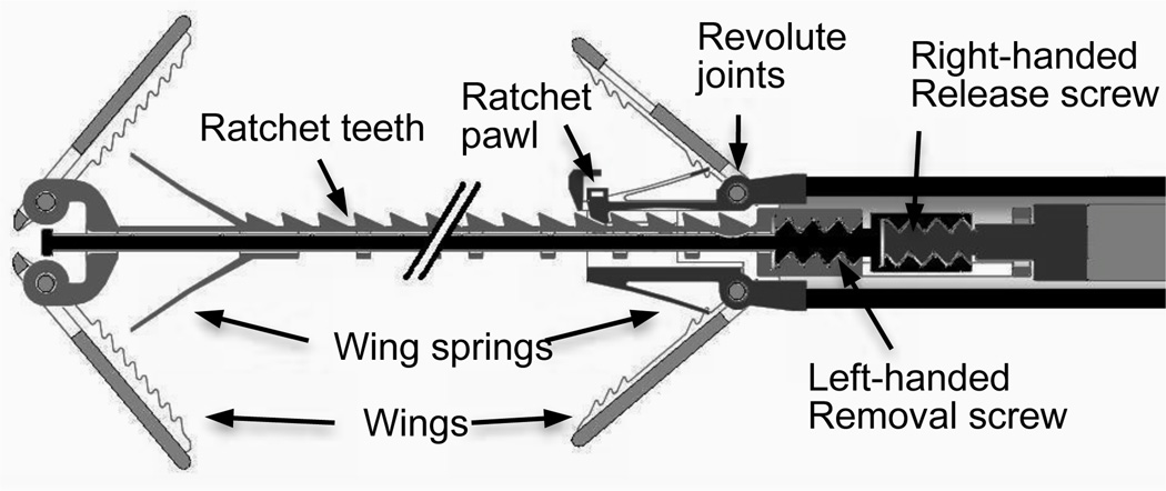
The mechanism that enables both device release as well as removal is depicted conceptually in Fig. 7. During normal operation, the rod shown in Fig. 6 prevents the distal wings from folding outward. Once it is determined that the device is appropriately deployed, the device is released by rotating the threaded deployment wire counterclockwise while the deployment tube prevents the device from rotating.
Fig. 7.
Screw mechanism concept for device removal by release of distal wings.
If the device must be removed, however, the deployment wire is rotated clockwise with respect to the deployment tube. This causes rotation of the left-handed screw threads between the rod and rail of Fig. 6 and Fig. 7. The rod translates in the proximal direction with respect to the rail thus allowing the distal wings to fold outward and so be retracted through tissue without damage and into the robot.
B. Compliance and Strength
The design specifications for bending compliance and pullout force are challenging and conflicting requirements. The bending compliance requirement is for the device to be delivered through our concentric tube robots designed for beating-heart surgery in the right atrium. The design requirement is based on the innermost robot tube that has a 1.6 mm ID and a radius of curvature of 30 mm. The main components affected by this requirement are the rail and rod (Fig. 6). To ensure sufficient strength of the rail’s ratchet teeth and retaining rings, it was designed to bend with respect to the cross section axis parallel to the ratchet teeth. FEM analysis was used to ensure that stresses were significantly less than the yield stress of NiCo (~900 MPa).
As described in the previous section on device removal, the rod prevents the distal wings from folding outward during normal operation. This means that when the device is pressing tissue together between the distal and proximal wings, the rail is experiencing a tensile load while the rod is experiencing a compressive load. The tensile load in the rail is given by the desired pull-out force of 1 N. Assuming that the pull-out force is applied to the midpoint of the distal wings, the 3:1 ratio of moment arms means that the rod must support a compressive column load of 3 N. The rail and base components provide substantial bracing for the rod acting as a column. The assumption of hinged-hinged boundary conditions was used to conservatively select a rod diameter of 150 microns to avoid failure by buckling.
Other parts that required FEM analysis to ensure a design of sufficient strength to meet the pull-out force requirement include the ratchet teeth, the ratchet pawl, the four revolute joints of the wings and the wings themselves (Fig. 6).
C. Flexure Design
While the device design uses traditional macro-scale mechanical components such as screws and revolute joints, it also utilizes flexure joints to accomplish sub-millimeter motion. For example, the ratchet pawl deflects 100 microns as it slides over the ratchet teeth. Its design required that it be flexible enough to achieve this deflection without yielding while also being sufficiently stiff to prevent deflection-induced ratchet disengagement when the device is loaded to the desired pull-out force.
Flexure springs were also designed to force the wings to rotate open by 30 degrees as the device is extended from the robot tube (Fig. 6). The springs are necessary to ensure that the wings do not remain stuck against the rail and rod of the device. It was determined that if they are initially spread by at least 30 degrees from the folded configuration then contact forces with the tissue during ratcheting would cause them to open fully. To achieve this angular rotation, the wing springs deflect by 160 microns when the wings are folded. FEM analysis was used to size the springs such that Von Mises stress remained below the yield stress.
IV. Experiments
To evaluate the device, three types of experiments have been conducted. First, the mechanical strength of the device was measured by testing three devices to failure. Next, the devices were tested in vivo using a manual deployment system that enabled device delivery through the wall of the beating heart using an open-chest model. The third set of experiments describe bench-top robotic deployment.
A. Pull-out Force Testing
Due to the modest pressure difference between the right and left atria, an approximation device experiences much less tensile load than the design specification of 1 N. Nevertheless, experiments were performed to evaluate the strength of the approximation device.
Such a repair can fail in one of two ways. The approximated tissue may tear or the device may fail. In the case of a surgical repair, the septal tissue will always tear before the suture fails. The device wingspan of 4 mm and wing width of 1 mm are comparable to the width of a suture bite and the width of the suture, respectively. Thus, repair failure using the MEMS approximation device can be evaluated based on strength testing of the device itself.
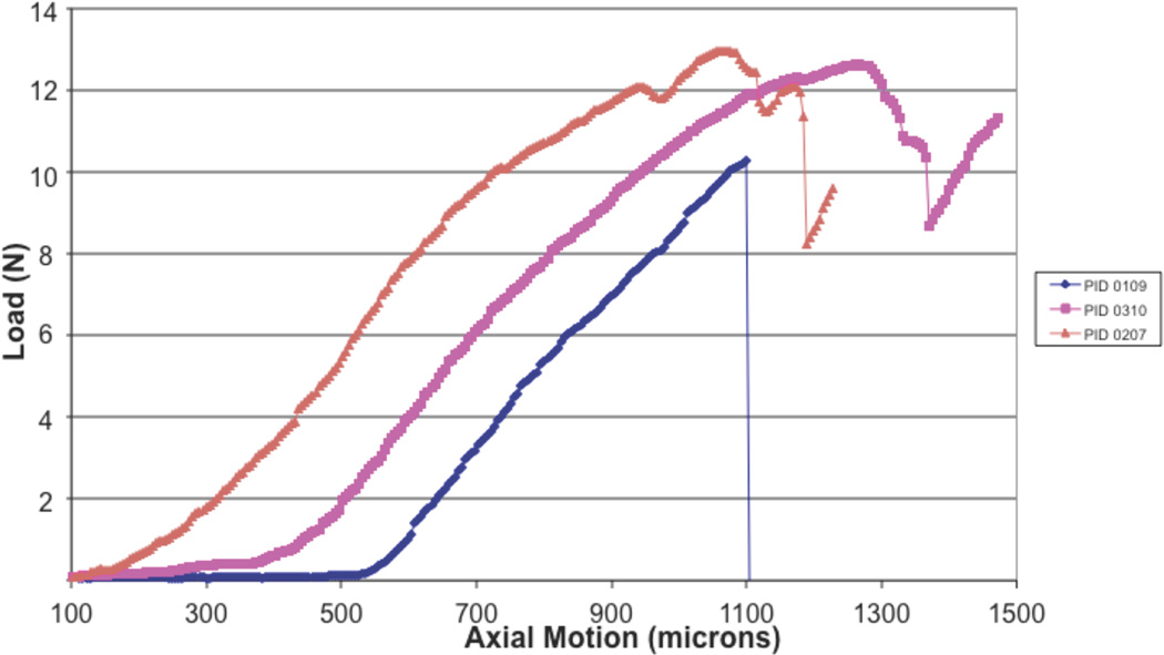
Three devices were tested to failure as shown in Fig. 8. A tensile testing machine was used with a test fixture consisting of parallel metal plates with 1.5 mm diameter holes through which the rail and rod of Fig. 6 passed. As shown, all devices failed at loads above 1 N. The failures all corresponded to over-rotation of the wings.
Fig. 8.
Device strength testing. Load versus displacement to failure.
B. Manual In Vivo Device Testing
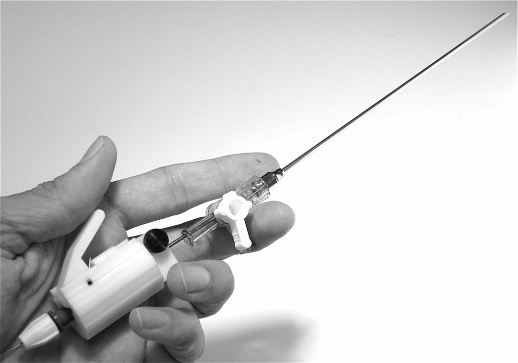
Prior to integration with the robot delivery system, the approximation device was first successfully tested by manually inserting the device through the heart wall using an in vivo open-chest porcine model [15]. A tunnel-like PFO was initially created under video-assisted cardioscopy and epicardial echocardiography. For PFO closure, the manual deployment system was advanced toward the point of septal puncture under 2D and 3D echocardiography guidance. Once the septum was penetrated, fluoroscopy was used for device deployment and ratcheting. The manual insertion instrument is shown in Fig. 9.
Fig. 9.
Manual device for transmural PFO approximation.
C. Robot-Assisted Deployment
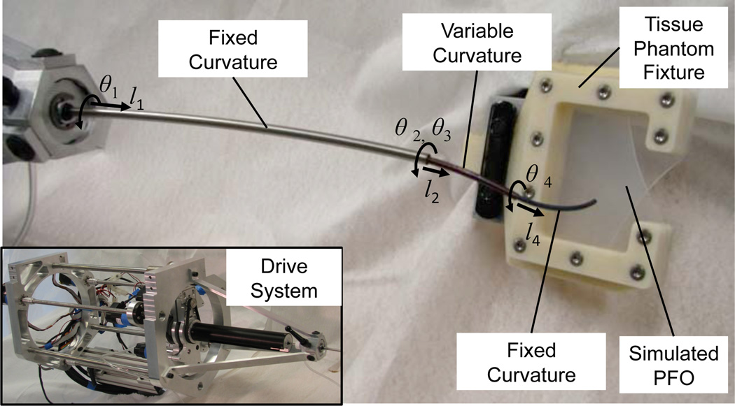
In preparation for in vivo robot experiments, a set of experiments were conducted on the bench top using the concentric tube robot and simulated PFO shown in Fig. 10. The robot possesses seven degrees of freedom and is comprised of three telescoping sections. The proximal section is of fixed curvature and is used to navigate from the point of percutaneous entry to the internal jugular into the right atrium. The distal sections of the robot are of variable and fixed curvature, respectively, and are the sections responsible for positioning and deploying the approximation device.
Fig. 10.
Bench top robotic PFO closure
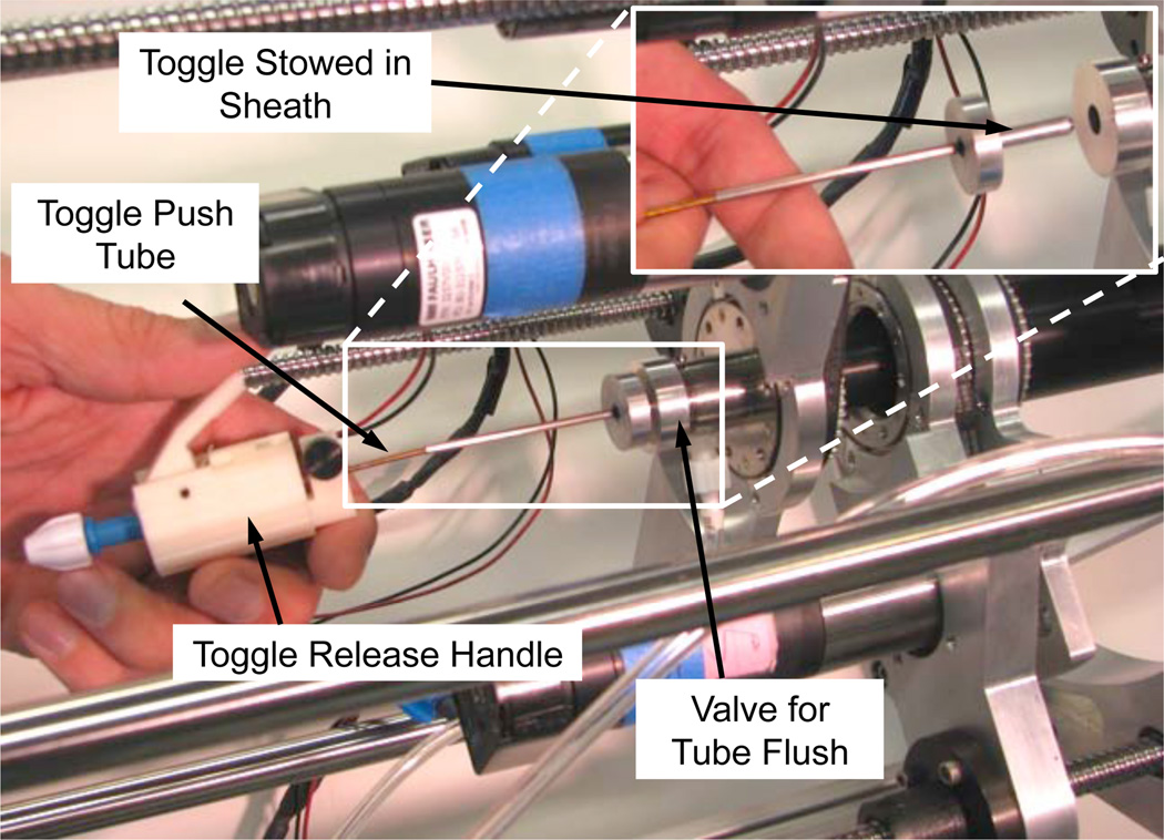
The drive system shown in the inset of Fig. 10 was modified to enable sequential rear-loading of the tissue-puncturing stylet and approximation device. This process is depicted in Fig. 11. Since the tubes must be flushed with saline to remove air and thus avoid the formation of emboli, a seal and flush system was incorporated. The toggle is protected during insertion through the seal by an enclosing sheath as depicted in the inset. Once through the seal, the toggle slides through a tube of constant diameter to reach the distal end of the robot.
Fig. 11.
Rear-loading system for puncturing stylet and approximation device.
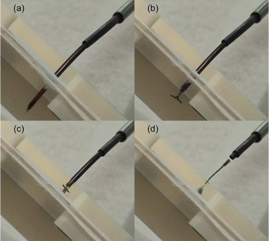
The simulated PFO was created using two separate tissue phantom layers made from a fabric that was selected based on surgeon feedback to produce a realistic force of resistance during puncture and delivery. Fig. 12 depicts the phantom as well as the deployment sequence during a closure experiment.
Fig. 12.
Robotic delivery of approximation device. (a) Phantom puncture with stylet, (b) Deployment of distal wings, (c) Deployment of proximal wings and ratcheting to approximate phantom tissue layers, (d) Release of device.
When deployed, the wings of the device are flush with the tissue surface and thus will be quickly encapsulated in tissue. This is especially important on the distal side (i.e., left atrium) to avoid the formation of emboli. After release, the ratchet rail is shown protruding in a manner comparable to the suture knots of a surgical repair (Fig. 12(d)).
V. Conclusion
The concept of adapting procedures and tooling to the capabilities of the robot is what made robots successful in manufacturing. The approach can be applied equally effectively to medical applications. This approach has been applied here to the use of concentric tube robots for a specific intracardiac procedure through the design of a tissue approximation device for PFO closure. The device was manufactured using a metal MEMS process that enables the fully-assembled fabrication of macro-scale mechanisms in millimeter-scale devices. This has the effect of reducing the complexity of the robot motions required to deploy it. Future in vivo robotic trials are planned.
Acknowledgments
This work was supported by the National Institutes of Health under grants R01HL073647 and R01HL087797.
Contributor Information
Evan J. Butler, Email: Evan.Butler@childrens.harvard.edu, Cardiovascular Surgery, Children’s Hospital Boston, Harvard Medical School, Boston MA 02115 USA.
Chris Folk, Microfabrica, Inc., Van Nuys, CA, USA.
Adam Cohen, Microfabrica, Inc., Van Nuys, CA, USA.
Nikolay V. Vasilyev, Email: Nikolay.Vasilyev@childrens.harvard.edu, Cardiovascular Surgery, Children’s Hospital Boston, Harvard Medical School, Boston MA 02115 USA.
Rich Chen, Microfabrica, Inc., Van Nuys, CA, USA.
Pedro J. del Nido, Email: Pedro.DelNido@childrens.harvard.edu, Cardiovascular Surgery, Children’s Hospital Boston, Harvard Medical School, Boston MA 02115 USA.
Pierre E. Dupont, Email: Pierre.Dupont@childrens.harvard.edu, Cardiovascular Surgery, Children’s Hospital Boston, Harvard Medical School, Boston MA 02115 USA.
References
- 1.Madhanir A, Niemeyer G, Salisbury JK., Jr The Black Falcon: A Teleoperated Surgical Instrument for Minimally Invasive Surgery. IEEE/RSJ Int. Conference on Intelligent Robots and Systems; Victoria, B.C., Canada. 1998. pp. 936–944. [Google Scholar]
- 2.Simaan N, Xu K, Kapoor A, Wei W, Kazanzides P, Flint P, Taylor R. A System for Minimally Invasive Surgery in the Throat and Upper Airways. Int. J. Robotics Research (special issue on medical robotics) 2009;28(9):1134–1153. doi: 10.1177/0278364908104278. [DOI] [PMC free article] [PubMed] [Google Scholar]
- 3.Mareedu RK, Shah MS, Mesa JE, McCauley CS. Percutaneous closure of patent foramen ovale: a case series and literature review. Clin Med Res. 2007;5(4):218–226. doi: 10.3121/cmr.2007.764. [DOI] [PMC free article] [PubMed] [Google Scholar]
- 4.Meeker DC, Maslen EH, Ritter RC, Creighton FM. Optimal realization of arbitrary forces in a magnetic stereotaxis system. IEEE Trans. on Magnetics. 1996;32(2):320–328. [Google Scholar]
- 5.Camarillo D, Milne C, Carlson C, Zinn M, Salisbury JK. Mechanics Modeling of Tendon-Driven Continuum Manipulators. IEEE Trans. Robotics. 2008;24(6):1262–1273. [Google Scholar]
- 6.Camarillo D, Carlson C, Salisbury K. Configuration Tracking for Continuum Manipulators with Coupled Tendon Drive. IEEE Trans. Robotics. 2009;25(4):798–808. [Google Scholar]
- 7.Jayender J, Patel RV, Nikumb S. Robot-assisted active catheter insertion: Algorithms and experiments. International Journal of Robotic Research. 2009;28(9):1101–1117. [Google Scholar]
- 8.Ikeuchi M, Ikuta K. Development of pressure-driven micro active catheter using membrane micro emboss following excimer laser ablation (MeME-X) process. IEEE Int Conf Robotics and Automation; Kobe, Japan. 2009. pp. 4358–4361. [Google Scholar]
- 9.Dupont P, Lock J, Itkowitz B, Butler E. Design and Control of Concentric Tube Robots. IEEE Trans Robotics. 2010;26(2):209–225. doi: 10.1109/TRO.2009.2035740. [DOI] [PMC free article] [PubMed] [Google Scholar]
- 10.Rucker D, Webster R, III, Chirikjian G, Cowan N. Equilibrium Conformations of Concentric-tube Continuum Robots. Int J Robotics Research. 2010;29(10):1263–1280. doi: 10.1177/0278364910367543. [DOI] [PMC free article] [PubMed] [Google Scholar]
- 11.Dupont P, Lock J, Itkowitz B. Real-time Position Control of Concentric Tube Robots; Conf Proc IEEE International Conference on Robotics and Automation; 2010. pp. 562–568. [DOI] [PMC free article] [PubMed] [Google Scholar]
- 12.Rucker DC, Jones BA, Webster RJ., III A Geometrically Exact Model for Externally Loaded Concentric-Tube Continuum Robots. IEEE Trans Robotics. 2010;26(5):769–780. doi: 10.1109/TRO.2010.2062570. [DOI] [PMC free article] [PubMed] [Google Scholar]
- 13.Lock J, Laing G, Mahvash M, Dupont P. Quasistatic Modeling of Concentric Tube Robots with External Loads. IEEE/RSJ Intelligent Robots and Systems (IROS) 2010:2325–2332. doi: 10.1109/IROS.2010.5651240. [DOI] [PMC free article] [PubMed] [Google Scholar]
- 14.Mahvash M, Dupont P. Stiffness Control of Continuum Surgical Manipulators. IEEE Trans. Robotics. 2011 doi: 10.1109/TRO.2011.2105410. in press. [DOI] [PMC free article] [PubMed] [Google Scholar]
- 15.Suematsu Y, Martinez JF, Wolf BK, Marx GR, Stoll JA, DuPont PE, Howe RD, Triedman JK, del Nido PJ. Three-dimensional echo-guided beating heart surgery without cardiopulmonary bypass: atrial septal defect closure in a swine model. J Thorac Cardiovasc Surg. 2005 Nov;130(5):1348–1357. doi: 10.1016/j.jtcvs.2005.06.043. [DOI] [PubMed] [Google Scholar]


