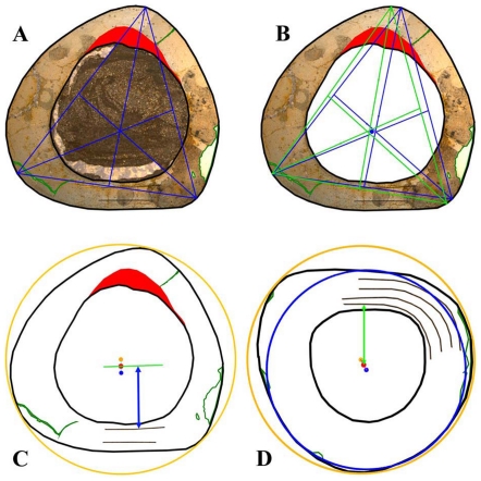
Figure 26. Sketches showing important steps to gain a standardized midpoint in cross sections for the measurement of distances between this midpoint and the external border of each growth cycle.
A–C: Late juvenile femur GZG.V 6590 28: A – First triangle with its vertices on the utmost extremities of each corner; B – Second triangle with vertices extrapolated from the respective opposing straight walls. The blue point in the centre is the midpoint from both triangles; C – The final midpoint of the cross section is derived from the blue midpoint of the triangles and the orange midpoint of the sketched circle. The green line lies parallel to the course of the growth cycles and the distances (e.g. blue double arrow) are then measured perpendicular to the cycles in the posterolateral part of the posterior wall. D – Late juvenile tibia GPIT/RE/3724: The midpoints of an inner and an outer circle (blue and orange, respectively) are used to get the final midpoint (red) for measuring the growth cycle distances. All sketches are not scaled, but consistently oriented with the anterior direction at the top and the medial direction at the left. The red area in A–C represents the anterior CCCB-wedge. Lines in green mark damage of the cross sections.

