Figure 4.
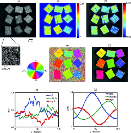
Results from an imaging experiment in which nine fibrous samples were attached to the surface of an isotropic light scattering phantom. The fibrous samples were rotated so that the orientations of the fibers for each sample were different. (a) A black and white photograph of the entire sample. Inset is a confocal reflectance image of one of the fibrous samples showing the alignment of the microscopic fibers. (b) Image of the SOI indicating that the fibrous samples have more anisotropic scattering than the underlying phantom. (c) Thresholded image of the SOI superimposed over the black and white photograph. (d) Color coded image of the orientation of the light scattering structures in which each color represents a different angle as denoted by the color wheel to the left. (e) Thresholded image of the structure orientation superimposed over the black and white photograph. (f) Plots of the measured amplitude |g(φ)| as a function of angle for three individual CCD pixels corresponding to the center of three fibrous samples in the bottom row. (g) Plots of the same CCD pixels in (f) but after the spatial and angular filtering described in the text.

