Figure 3.
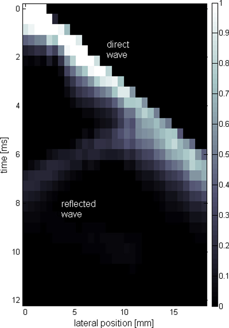
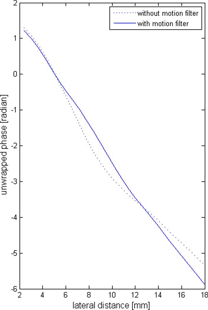
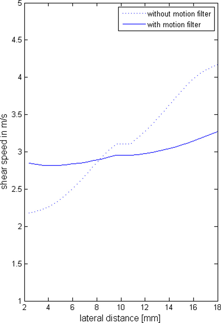
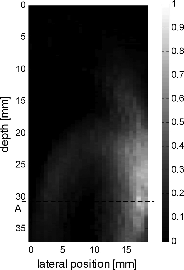
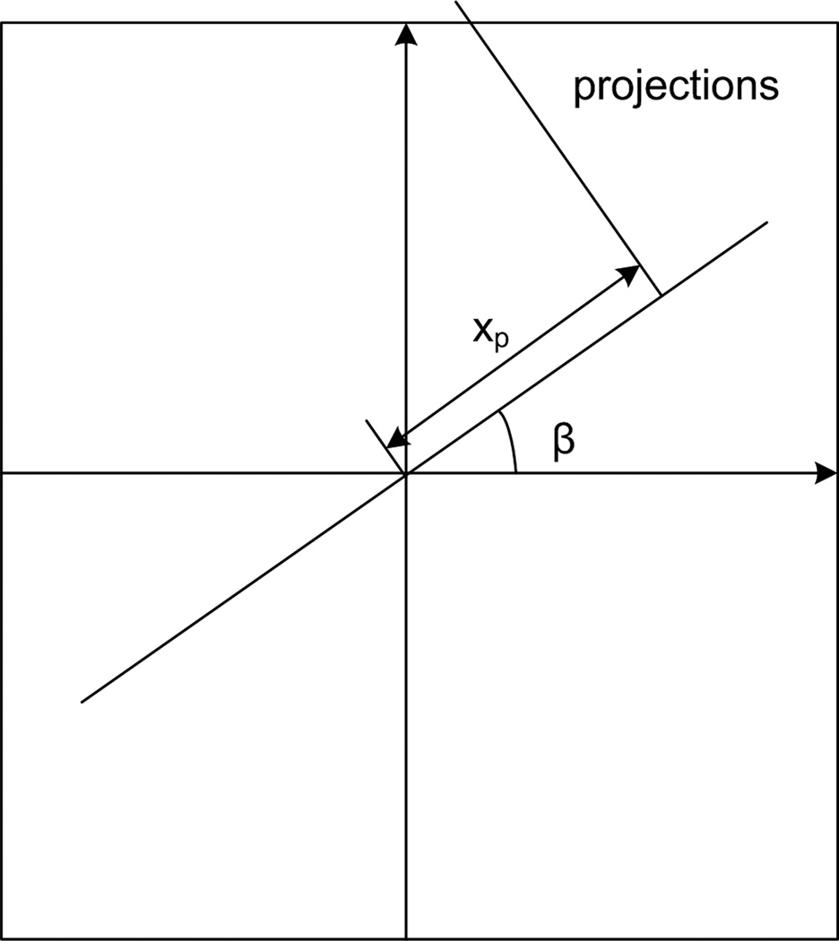
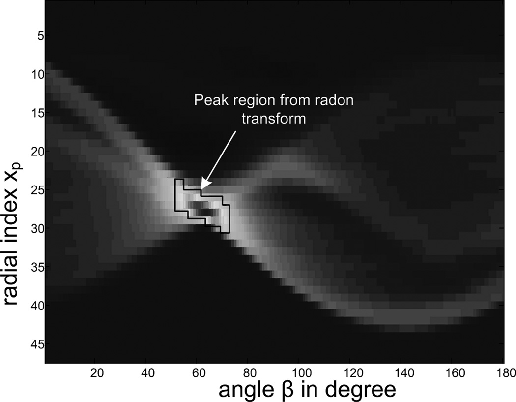
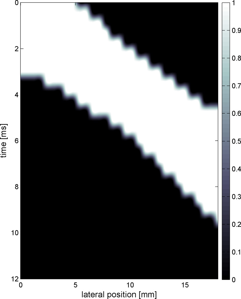
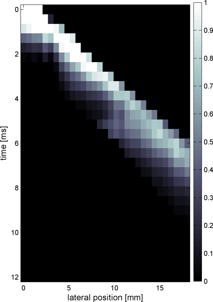
An example of shear wave displacements from radiation force with reflection. (a) A frame of the shear wave displacements shows a reflected wave. An image slice at depth A of (a) is shown in (b), where the direct wave is clearly discernible from the reflected wave. (c) illustrates the concept of Radon transformation with angle β and radial distance xp. (d) displays the result of radon transform. The peak region is marked. Each of the points inside the peak region converts to a single line in the original image. Combining these lines and smoothing produces a final motion mask shown in (e). (f) shows the motion-filtered image. The phase distribution and the estimated shear speed are shown in (g) and (h), respectively, with and without motion filtering.

