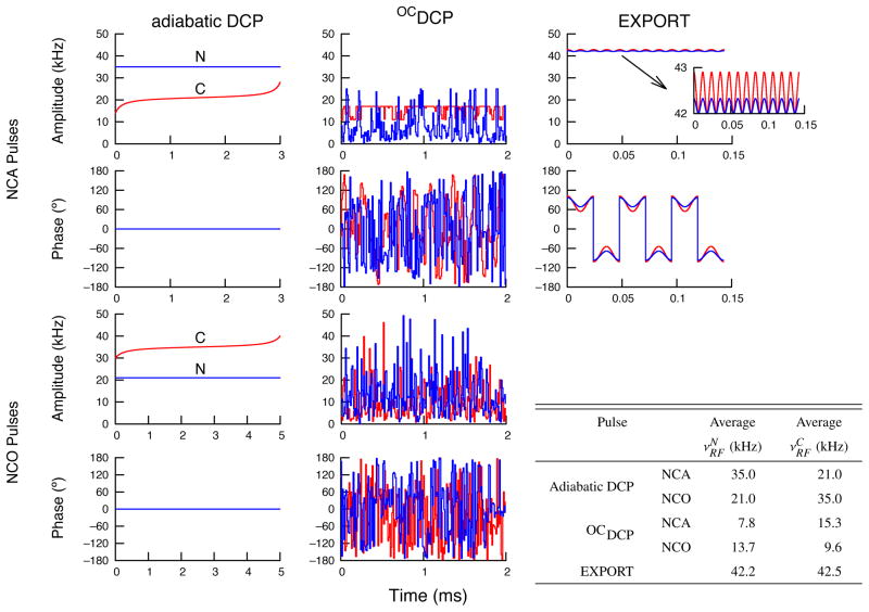
Figure 1.
Amplitude and phase profiles for the 15N-13C transfer pulses used in this paper for experiments at 700 MHz for 1H with νr=14 kHz. The inset table provides the average RF amplitude (in kHz) for each channel of each pulse. Data are shown in blue for the 15N channel and in red for the 13C channel. Adiabatic DCP is only amplitude modulated (phase is set to 0° for both channels). For EXPORT, the same sequence is used for both NCA and NCO transfers with only a change in the carrier frequency. In addition, for EXPORT only the basic building block (which is two rotor cycles long) is shown; the number of times that this block was repeated was experimentally optimized for each sample to maximize transfer efficiency.

