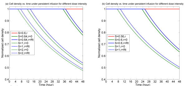
Figure 2.
Temporal profiles of cell density at specific spatial locations for persistent infusion for different dose intensities. (a) Bistable switch case, (b) Monostable switch case. It is noted in the current and following figures that multiple plots might overlay one another at cell density equal to 1. In each of the plots, the red line indicates the level of cell density (spatially uniform) for a below threshold dose, showing that no killing results in this case.

