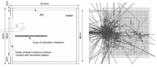
Figure 1.
Geometry of the Water Phantom. The two geometry types used for the simulation of the water phantom: left: solid box phantom with the measurement chambers inside (which are also out of water; 30 of the 40 chambers used in the calculations are shown) with one incoming neutron track; right: x-y-plane of the voxelised water phantom with tracks from 100 primary neutrons of the FRM II beam. For visualization purposes, a 2 cm voxel size was used here, instead of the 2 mm used in the actual GEANT4 simulations.

