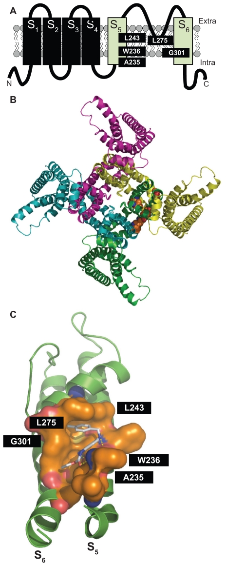
Figure 1.
Panel A shows the schematic topology of a single Kv7.2 subunit, with each of the six transmembrane regions indicated. The green cylinders correspond to the S5 and S6 transmembrane regions. The amino acids involved in retigabine binding are indicated. Panel B shows a top view of the overall structure of the channel formed by four identical Kv7.2 subunits, with one retigabine molecule bound. Panel C shows an enlarged view of the retigabine binding site with the retigabine molecule docked into the channel cavity as obtained with ArgusLab 4.0.1 (Planaria Software LLC, Seattle, WA; available at http://www.arguslab.com). The residues involved in retigabine binding are indicated. The dashed yellow lines indicate the polar contacts between retigabine and the residues A235 and W236. Three-dimensional models of Kv7.2 subunits were generated by homology modelling using known structures of potassium channel subunits available in the Protein Data Bank), using SWISSMODEL, a program that performs automated sequence-structure comparisons, as previously described.92 The model generated was analyzed using both the DeepView module of Swiss-PDBViewer (version 3.7, available at http://www.expasy.ch/spdbv/) and PyMOL (available at http://pymol.sourceforge.net/). In the present study, the homology model was built using the template structure (2R9RH) for a chimeric channel in which the voltage-sensor paddle (corresponding to the S3b–S4 region) of Kv2.1 was transferred into the Kv1.2 subunit.93

