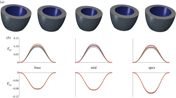
Figure 4.
Virtual phantom model: (a) phantom ventricle geometry discretized into tetrahedral elements; (b) comparison between the local strains of the virtual phantom computed with our code and the output provided by the finite-element solver. Given the axial-symmetry of the phantom, the finite-element solution consists in a single plot for the basal, mid and apical level of the phantom, respectively. (b) Navy blue, sect1; red, sect2; green, sect3; purple, sect4; sky blue, sect5; orange, sect6; red crosses, FEM.

