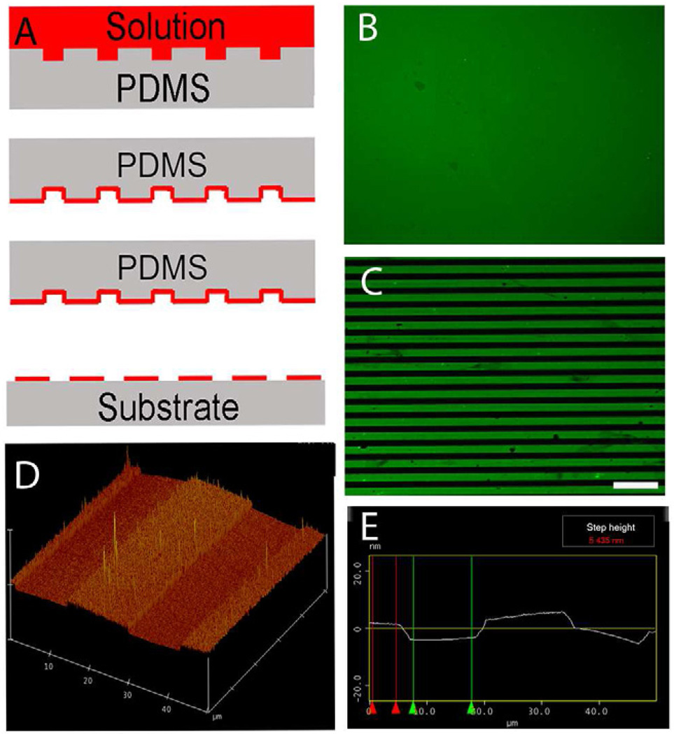
Fig. 1.
Microcontact printing. (A) Casting method for generating patterns of extracellular matrix ligand (red) onto the surface of glass coverslips. (B) Representative fluorescent image of stamped homogeneous laminin (LN) field (green). (C) Representative fluorescent image of micropatterned LN lane pattern consisting of alternating 15 µm wide LN lanes (green) and 15 µm wide lanes of the unpatterned glass coverslip surface (black). (D and E) Representative atomic force microscopy (AFM) image of the topography of a printed LN lane pattern on the glass coverslip. The light color plateaus represent the printed LN lanes and the darker color represents the bare glass coverslip surface. The step height between the printed LN lanes and bare coverslip surface is approximately 5nm as determined by AFM. Scale bar=100 µm.

