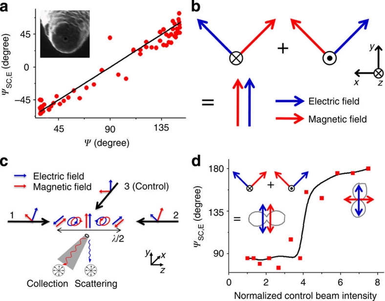
Figure 3. Measuring parallel electric and magnetic fields.
Measurements (λ=780 nm) of parallel electric and magnetic field polarizations for the demonstration of the magnetic field orientation as an independent entity. (a) The angle of polarization ψsc, E for the collection signal from a flat-bottomed near-field optical scanning microscopy (NSOM) probe plotted against ψ, showing that this probe is a magnetic field analyser. (b) Schematic for the generation of parallel electromagnetic fields using two counter-propagating, orthogonally polarized light. (c) Experimental schematic for the generation and measurement of parallel electromagnetic fields. Polarization on the probe aperture is controlled by applying an additional phase to beam 1. The collection signal is analysed by a linear polarizer in front of the detector. (d) Experimental control of magnetic field orientation by tuning the intensity of the control beam 3. Polar plots of the representative collection signal (grey) are shown in the inset, showing transition from the parallel electric and magnetic fields case to the normal case of perpendicular electric and magnetic fields.

