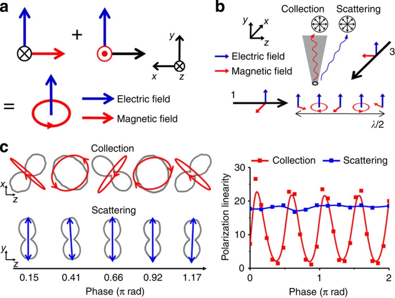
Figure 4. Measuring linearly polarized electric and circularly polarized magnetic fields.
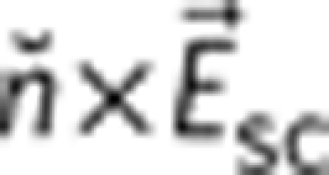
(a) Schematic for the generation of linearly polarized electric and circularly polarized magnetic fields using two orthogonally propagating light (λ=780 nm). (b) Experimental schematic for the generation and measurement of circularly polarized magnetic field along with linearly polarized electric field. (c) Polar plots for the collection (up) and scattering (down) mode signals. Magnetic field orientation (red) is obtained from the collection near-field optical scanning microscopy (NSOM) signal, via  , showing alternation between circularly polarized states and linearly/highly elliptically polarized states. Electric field polarization (blue) remains fixed along the y axis. Phase-dependent polarization linearity for the scattering and collection signal, in which the polarization linearity is defined as the intensity ratio of major axis polarization and minor axis polarization (right inset).

