Figure 2.
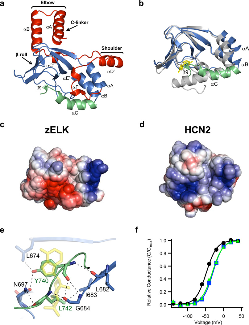
Structure of the C-linker/CNBHD. a, Ribbon representation of a monomer of the C-linker/CNBHD of zELK channels. b, Alignment of the CNBHD of zELK (the αC-helix is green and the rest is blue) and HCN2 (grey) channels10. cAMP in the HCN2 structure is yellow. c, d, Electrostatic potential surface of the CNBHD of zELK (c) and HCN2 channels (d), viewed in the same orientation as in Fig. 2b. e, Residues in the β-roll cavity interacting with residues Y740 and L742 of the intrinsic ligand. Dashed lines show both polar and non-polar interactions. cAMP from the HCN2 structure is shown in yellow. f, Representative conductance-voltage relations for wild-type (black), Y740A mutant (blue), and Δ740-742 mutant (green) zELK channels.

