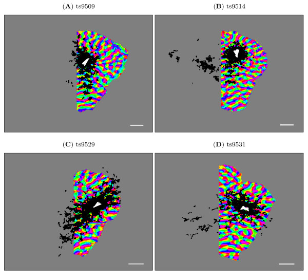
Figure 2.
Orientation preference maps with connections. The orientation preference map for all cases with the injection site (white) and bouton traces (black) overlaid. The direction of the white injection sites indicates the preferred orientation at these points. The boutons indicate horizontal connections originating at the injection sites and connecting to the bouton sites. The orientation preference maps have been rotated, flipped and truncated (see methods) to create right-handed co-ordinate systems aligned with visual space and the overlaid boutons and injection sites have been similarly transformed after alignment. Scale bar is 1 mm.

