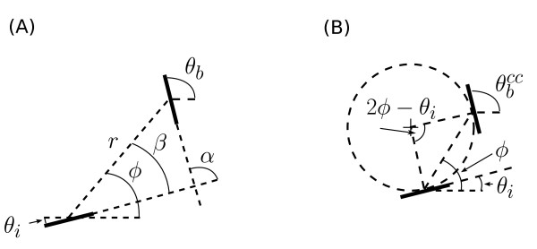
Figure 3.
Definition of terms. (A) is a diagram of the various definitions of orientation and position between the injection site and the bouton site used in the methods. (B) shows a representation of eq. 1 showing co-circularity. Two edges are co-circular when they lie tangent to a common circle. Given an injection site with orientation
 there is a unique orientation preference
 (for any ϕ) that is exactly co-circular with the injection site.

