
Figure 8.
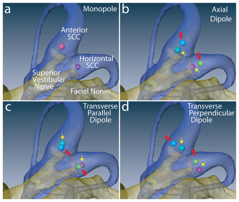

Figure 8a–d: Four idealized electrode configurations as applied in the anterior and horizontal semicircular canal ampullae. (a) Monopolar (active electrodes shown; distant reference electrodes not shown). (b) Axial dipole. (c) Transverse/Parallel dipole. (d) Transverse/Perpendicular dipole. Double red arrows in b–d indicate the active electrode, which is cathodic during the first phase of a symmetric, charge-balanced, biphasic constant-current pulse. e–h: Simulated fiber recruitment plots for each anterior canal case. Transverse/Parallel dipole outperforms other configurations with regard to selectivity.