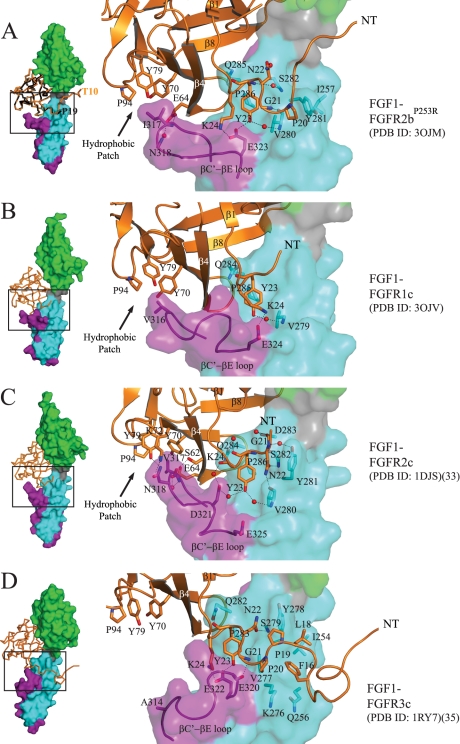
FIGURE 1.
Plasticity at the FGF1-D3 interface. A, left, Cα trace of FGF1 from the FGF1-FGFR2bP253R structure in space group P212121 (PDB code 3OJM) (in orange) is superimposed onto that of FGF1 from the FGF1-FGFR2bA172F structure in space group P32 (PDB code 3OJ2) (in black). The first ordered N-terminal residue in each FGF1 molecule is labeled. FGFR2b is shown as a surface, with D2 colored green, D2-D3 linker in gray, the common region of D3 in cyan, and the alternatively spliced portion of D3 in purple. This color scheme for the receptor is used throughout the paper including in supplemental Figs. 3, 4, 5, and 7. The FGF1-FGFR2bP253R structure in space group P212121 (PDB code 3OJM) is used for comparison with other FGF1-FGFR structures. Right, a close-up view of selected N-terminal and hydrophobic patch contacts of FGF1 with D3 of receptor in the FGF1-FGFR2bP253R crystal structure. FGF1 is shown as a ribbon diagram, and selected residues are rendered as sticks, with oxygen colored red and nitrogen colored blue. Water molecules are indicated as red spheres. This color scheme for atoms is used throughout the paper including in supplemental Figs. 4, 5, and 7. The location of the hydrophobic patch between FGF core and the βC′-βE loop of receptor is indicated by an arrow. B, the new FGF1-FGFR1c structure (PDB code 3OJV) displaying an ordered βC′-βE loop. Selected N-terminal and hydrophobic patch contacts of FGF1 with D3 of receptor are shown. C, selected N-terminal and hydrophobic patch contacts of FGF1 with D3 of receptor in the FGF1-FGFR2c crystal structure (PDB code 1DJS). D, selected N-terminal and hydrophobic patch contacts of FGF1 with D3 of receptor in the FGF1-FGFR3c structure (PDB code 1RY7). Note that Ala-314 in D3 of FGFR3c cannot make a strong hydrophobic contact with Pro-94, Tyr-79, and Tyr-70 in the FGF1 core, and as a result, the βC′-βE loop falls away from the core of the ligand.

