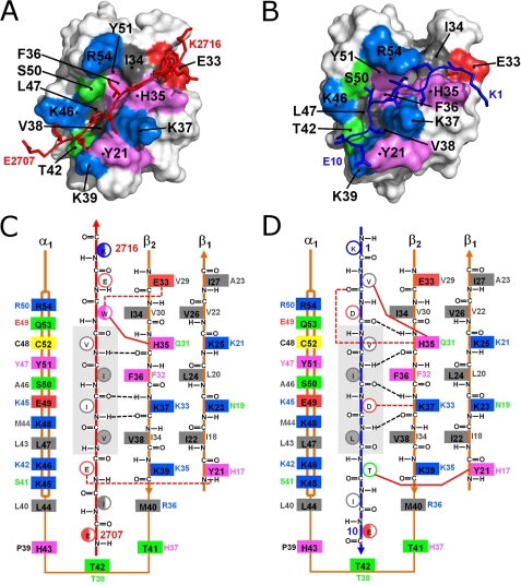
FIGURE 2.
Structural insights into SIM-SUMO1 interactions of two high-affinity SIMs bound in opposing orientations. A and B, surface representations of SUMO1 in complex with the M-IR2 (A) and PIASX (B) SIMs. The interacting residues in SUMO1 are colored according to amino acid type: positive (blue), negative (red), aromatic (violet), hydrophobic (gray), and polar (green). The red and dark blue stick models represent the bound M-IR2 and PIASX SIMs, respectively. C and D, schematic of the interactions between SUMO1 and the M-IR2 (C) and PIASX (D) SIMs, illustrating paralogue- and/or orientation-specific interactions. The two SIMs extend the β-sheet of SUMO1 in opposing orientations, antiparallel for M-IR2 and parallel for PIASX. The side chains of the SIMs are shown as circles, with open circles representing side chains pointing to the surface and filled circles representing side chains pointing toward the interior of the SIM binding groove on SUMO. The multiple conformations of Trp and the flexible terminal residues in the M-IR2 SIM are represented as half-filled circles. Listed beside each side chain of the SUMO1 residues (solid boxes) is the corresponding residue in SUMO2. All residues are colored as described in A and B. Black dashed lines indicate backbone hydrogen bonds between the SUMO1 β-strand and SIMs; red dashed lines represent hydrogen bonds or salt bridges involving side chains. Solid red lines represent key side chain interactions discussed in the “Results” section for Molecular Details of SUMO1-SIM Interactions. The central core region of the SIMs is shaded in gray.

