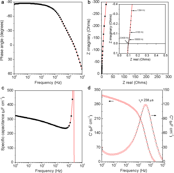
Figure 2. AC Impedance characterizations of ErGO-DLC.
(a) Plot of impedance phase angle versus frequency. (b) Complex plane plot of the impedance; inset: an expanded view in the region of high frequencies. (c) Plot of specific capacitance versus frequency using a series-RC circuit model. (d) Plot of the real or imaginary part (C′ or C″) of specific capacitance versus frequency.

