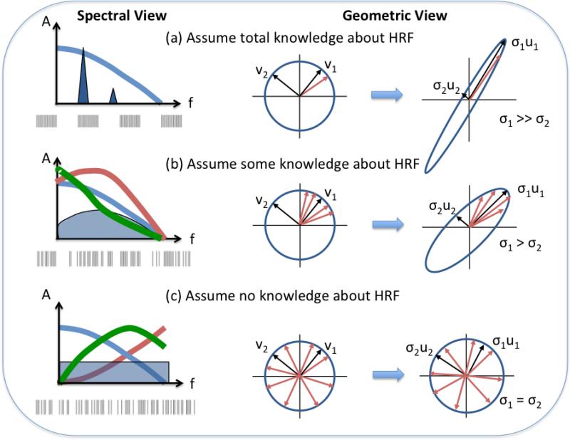
Figure 2.
Geometric and spectral views demonstrating the principles underlying optimal fMRI design. (a) When full knowledge of the shape of hemodynamic response function (HRF) is assumed , then the HRF is represented by the single red vector in the unit sphere. The optimal design will maximally amplify this vector, while minimizing the gain in other directions. This transforms the unit circle into a narrow ellipse. In the spectral domain, the HRF spectrum is fully specified (blue line), and the optimal design will place a spectral peak near the maximum of the spectrum. This is typically achieved with a block design , similar to the example design shown below the spectrum. (b) When some knowledge of the HRF shape is assumed (e.g. with the use of a limited set of basis functions), then the possible HRF vectors span a sector within the unit circle. The optimal design will focus on amplifying vectors within the sector, transforming the unit circle into an ellipse. In the spectral domain, there is a range of similar HRF spectral shapes, and the optimal design will tend to have a broadband spectrum (blue shaded area) that has relatively more energy where the average HRF spectra overlap. This is achieved with a semi-random design. An example design is shown below the spectrum. (c) When no knowledge of the HRF shape is assumed, then the possible HRF vectors span the entire unit circle. The optimal design must equally amplify all directions, such that the unit circle is transformed into another unit circle. In the spectral domain, there can be widely varying HRF spectral shapes, and the optimal design must therefore place equal energy at each frequency. This is achieved with a random or m-sequence design, as shown below the spectrum.

