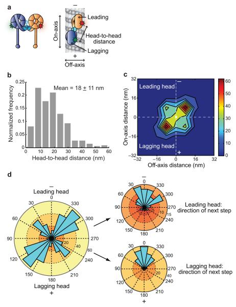
Figure 5.
Spatial arrangement of dynein motor domains during the two-head-bound state. (a) Schematic of dual-labeled DNA-dimerized dynein bound to a microtubule. Other arrangements of the motor domains are possible. Fluorophores are represented by red and green stars. (b) Histogram of dynein’s head-to-head distances during the two-head-bound state. N = 523. (c) Contour plot showing the left and right asymmetry between the leading and lagging heads. Orientation of the microtubule axis is vertical, as indicated by − and +, with the centroid position of each dynein molecule placed at the origin of the axes (white X). The number of occurrences of each position is indicated by the color bar on the right, with bin edges at 8 nm increments from −32 nm to +32 nm on both axes. N = 256 dimers or 512 heads. (d) On the left, an angle histogram of the position of the leading and lagging heads of individual dynein dimers relative to their respective centroid position (placed at the origin of the axes). Locations to the left or right of the direction of motion are between 0° and 180°, or 180° and 360°, respectively. 64% of the leading heads are to the right of the microtubule axis. N = 256 dimers or 512 heads. On the right, the angular distributions of the next step taken by the leading (top) or lagging (bottom) head. Steps between 90° and 270° are backwards steps.

