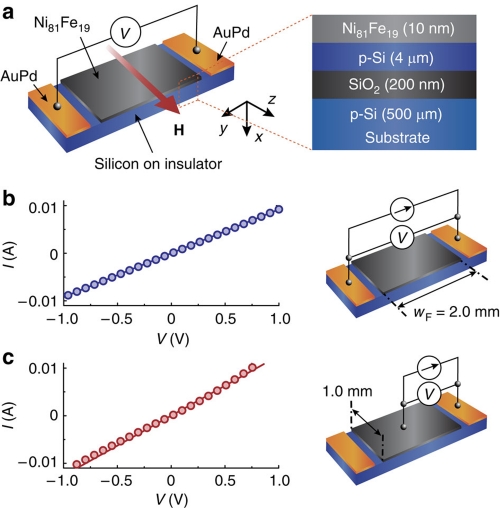
Figure 1. Experimental set-up.
(a) A schematic illustration of the Ni81Fe19/p-Si film used in this study. H represents an external magnetic field. (b) Current-voltage (I–V) characteristic measured for the Ni81Fe19/p-Si film, where the two electrodes are attached to the AuPd layers. wF is the length of the Ni81Fe19 layer. (c) I–V characteristic measured for the Ni81Fe19/p-Si film. The two electrodes are attached to the Ni81Fe19 layer and AuPd layer, respectively.

