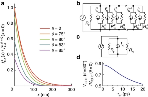
Figure 4. Spin current relaxation.
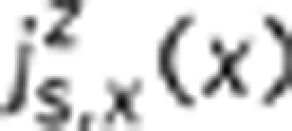
(a) The spin current density  generated by the spin pumping for τsf=9 ps. Here
  is the spin current density at the interface when the external magnetic field is applied along the film plane (θ=0). The parameters used for the calculation are shown in the text. (b) An equivalent circuit model of the Ni81Fe19/p-Si film. RF is the electrical resistance of the Ni81Fe19 layer. (c) A simplified equivalent circuit model of the Ni81Fe19/p-Si film. (d) The spin relaxation time τsf dependence of the ISHE signal VISHE at θ=80° calculated from equation (5).

