
Fig. 2.
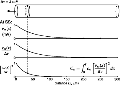
Illustration of the clamp-weighted capacitance,  , in a single finite cable. The cable is voltage-clamped at the left end (top panel). Once the voltage-clamp has come to steady state (bottom three panels), the voltage in the cable is described by a hyperbolic cosine function (Eq. (15)). The fraction of the voltage-clamp step “felt” at any point in the cable is given by the fraction
  (third panel). The weight used in the calculation of
  is given by the square of this fraction (bottom panel).
  is calculated by dividing the surface area of the membrane into many slices (shown in top panel), each of which has a capacitance and a weight associated with it (dashed line).
  is given by the weighted sum of the capacitance of all of these slices. Because the weight varies continuously, this sum is given by an integral (inset)