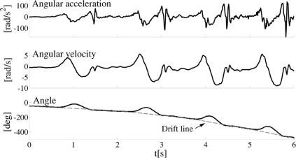
Figure 3.
Joint angle (bottom panel) and angular velocity (middle panel) obtained by numerical integration of the measured acceleration of the segment (top panel). Dashed line envelope on the bottom panel is fitted through the points where the knee should be fully extended with zero degree joint angle. However, due to the integration drift, instead of remaining approximately constant, this line has a parabolic shape.

