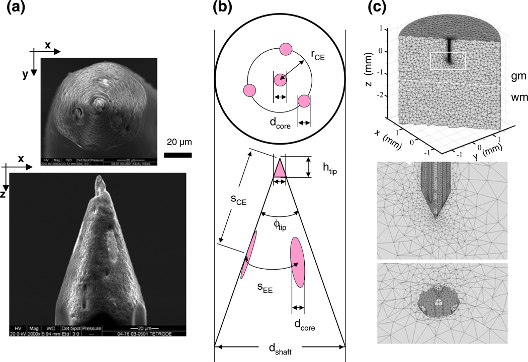
Fig. 6.
The geometry of a Thomas tetrode and its finite element model. This tetrode is the first one listed in Table 1. (a) Scanning electron microscopy images of the cleaned, untreated tip of the tetrode with axial view (top) and lateral view (bottom). The lighter contact surfaces of the PtW wire leads contrast well with the quartz coat. (b) The critical geometry parameters used in the tetrode models (defined and listed for each reconstructed tetrode in Table 1). (c) The tetrahedral mesh of the finite element model of the probe-brain system, viewed in three cross-sections; top, vertical on-axis cut showing overall dimensions; middle, same cut but zoomed-in on the tetrode tip area where elements representing the lead wires are visible; and bottom, cut in the x-y plane at the z-level where the core wires are exposed as contacts. Note that element size varies extensively; it is smallest near the tetrode tip

