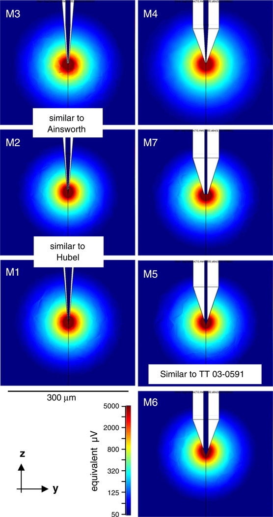
Fig. 9.
The lead fields of sharp electrodes modeled with a wide variety of tip shapes. Spatial scale and field strength are as in Fig. 8. Lead field geometry depends only weakly on the details of the tip geometry. The radius of the lead fields defined at a criterion field strength (or equivalent signal strength) is weakly anti-correlated with exposed tip area (models are vertically ordered with increasing tip area) and with the cone angle of the shaft, and does not depend significantly on the cone angle of the exposed tip. Most notably, the typical lead fields of our tetrodes (e.g., M5) are very similar in size to those of typical sharp electrodes (all other panels). Specifically, M1 and M2 are similar to tips fabricated by Hubel (Hubel 1957), and M2 and M3 are similar to tips fabricated by Ainsworth (Ainsworth et al. 1977). The varied geometry parameters and the resulting field radii are summarized in Table 3. Other details of the lead field modeling were the same as used for the tetrodes (see Fig. 8) and text

