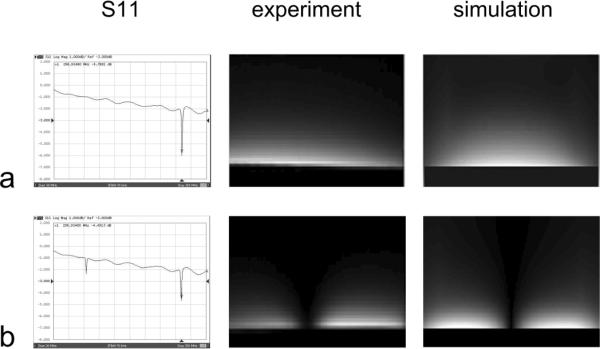
Fig. 3.

S11 plots and B1 profiles from experiment and simulation results of (a) primary harmonic microstrip resonator and (b) second harmonic microstrip resonator. The image patterns indicate the current or magnetic field distribution of the first and second harmonic resonance in a microstrip resonator.
