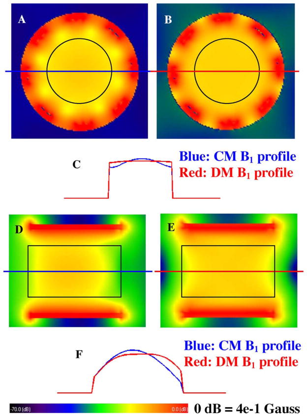
Fig. 8.
FDTD simulation results of the B1 distribution of the double-tuned CMDM volume coil at 7T in the loaded case. The black circles in (a) and (b) and black rectangles in (d) and (e) denote the phantom position. (a) Axial plane B1 distribution of the common mode channel for 1H. (b) Axial plane B1 distribution of the differential mode channel for 13C. (c) 1-D plot of the axial plane B1 distribution, blue line and red line denote the 1H and 13C, respectively. (d), (e) Sagittal plane B1 distributions of the common mode channel for 1H and the differential mode channel for 13C. (f) 1-D profile of the sagittal plane B1 distribution, blue line and red line denote the 1H and 13C respectively. It is shown that for 13C channel with the differential mode operating at 75 MHz, homogeneous B1 field distribution was obtained in both axial and sagittal directions, while for 1H channel with the common mode operating at 300 MHz, although “dielectric resonance” effects at ultrahigh fields distort the B1 field, a fairly homogeneous B1 distribution was still obtained in this case.

