Table 3.
Simulation of fault occurrence.
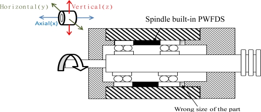
| Case 1. The excessive dimension error of the spindle parts |
Implementation: During spindle production, a part with the incorrect dimensions was assembled at the spindle. |
 | |
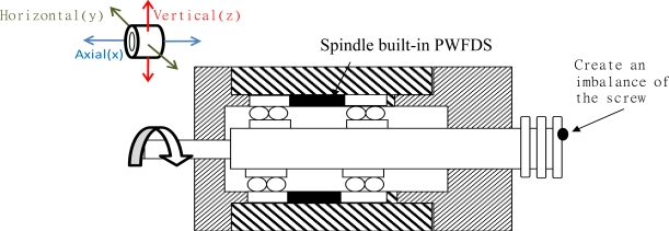
| Case 2. Unbalanced spindle |
Implementation: Attach a 5 g screw to the rotor of the spindle to create an imbalance in the spindle system. |
 | |
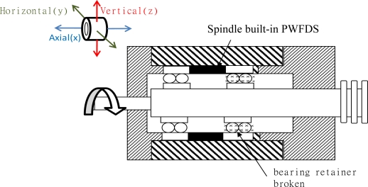
| Case 3. Damage to the bearing of the spindle |
Implementation: Place a abrasion bearing retainer that presents a workable bearing inside the spindle where embedded fault diagnosis is installed. |
 | |
