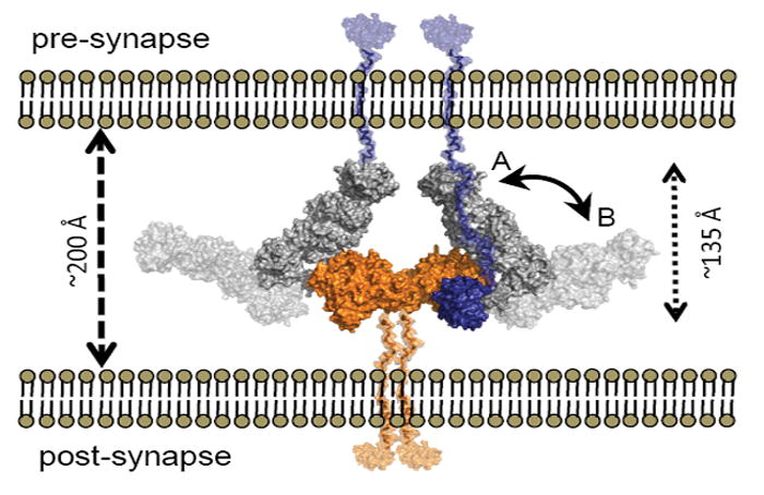
Figure 7. Model of the α-NRXN:NLGN Complex at the Synapse.

Overlays of α-NRXN_2-6 onto β-NRXN-1 as bound to NLGN-1 or -4 suggests a possible position for the α-NRXN:NLGN complex in the synaptic cleft. The overlaid complex is shown with the C-termini of α-NRXN and NLGN oriented towards the pre- and post-synaptic membranes, respectively. In this conformation the N-terminal domains lay to the pre-synaptic membrane (conformation A, non-transparent surface,). Flexibility at the hinge point between LNS 5 and EGF 3 could allow segmental motion of the α-NRXN_2-6 long arm towards a fully linear conformation of the extracellular region, moving the N-terminal domains in closer proximity to the post-synaptic membrane (conformation B, transparent surface). The relative position of the N-terminal domains is likely to confer selectivity for additional binding partners. The NLGN dimer is colored in orange, the α-NRXN LNS 2-EGF 3 in gray and LNS 6 in blue. Stalk domains for NLGN and α-NRXN_2-6, shown in semi-transparent orange and blue, respectively, were modeled into the figure.
