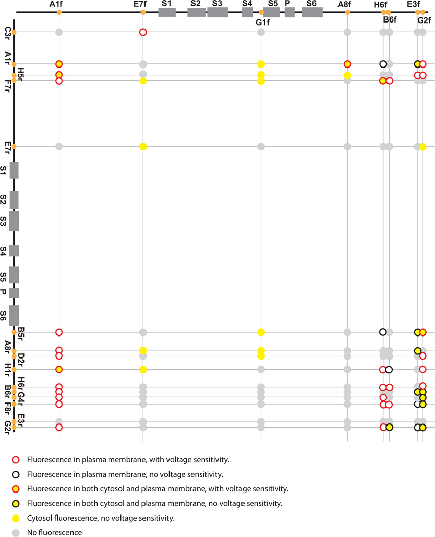
Figure 3. Insertion sites of the Venus split-cans in the Shaker channel, location of fluorescence and voltage sensitivity after co-transfection.
Top: Insertion sites of the split-can front half. Left: Insertion sites of the split-can rear half. The circles at the crossings represent the combinations of the two split-can halves. The colors of the circle surround and center indicate the fluorescence location and voltage-sensitivity. Red circle: fluorescence in plasma membrane, with voltage sensitivity; Black circle: fluorescence in plasma membrane, without voltage sensitivity; Red circle with yellow center: fluorescence in both cytosol and plasma membrane, with voltage sensitivity; Black circle with yellow center: fluorescence in both cytosol and plasma membrane, without voltage sensitivity; Solid yellow circle: cytosol fluorescence, without voltage sensitivity; Solid grey circle: No fluorescence.

