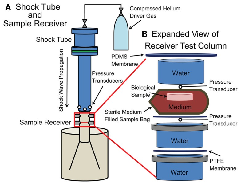
Figure 1.
Schematic of the shock tube with receiver. (A) A compressed helium source was connected to an adjustable driver section of the shock tube, which was aligned vertically over the sample receiver. In-air transducers were located at the exit of the shock tube. (B) The sample within a bag rested on top of a PTFE membrane within the fluid-filled sample receiver. Submersible transducers were located directly above the sample bag and below the PTFE membrane.

