Figure 3.
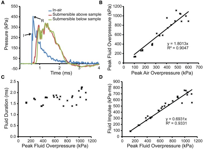
Characterization of the shock tube and fluid pressures with receiver in place. (A) An in-air pressure transducer (blue trace) located at the exit of the shock tube recorded pressure transients in-air for a shock produced from a 508-μm thick burst membrane with the receiver in place. The peak pressure in-air of the incident shock wave upon exiting the shock tube is denoted by “I,” and the peak pressure of the reflection is denoted as “R.” Two submersible transducers, located above or below the sample holder (including culture well, bag, and PTFE membrane; red and green traces, respectively) demonstrated the absence of attenuation through the in vitro set-up. (B) The peak overpressures from the submersible transducer below the sample holder were correlated to peak pressures measured by the in-air transducers. (C) The durations within the fluid-filled receiver were plotted against peak overpressures measured within the fluid-filled receiver, with no correlation to pressure found. (D) The impulses within the fluid-filled receiver were correlated to peak overpressures measured within the fluid-filled receiver and approximated using a linear fit.

