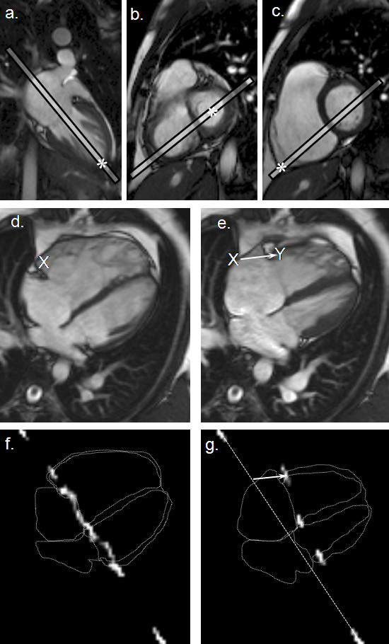
Figure 1.

Alignment of the 4-chamber cine and the tagging by CMR. Three points marked (*) in the scout images (a-c) were used to define the 4-chamber image plane (d and e). The post-subtraction CMR tissue tag images at end-diastole (f) and end-systole (g) are shown superimposed on outlines traced from the corresponding 4-chamber cine frames. The white arrow in panel e indicates the systolic displacement of the RV free wall tag relative to a dotted line that has been drawn between the motionless tagged regions of the chest wall. For manual measurement of RV basal free wall displacement, by using CMRtools, a marker (X) was placed in the RV free wall 5 mm from the atrio-ventricular groove at end-diastole (e) and copied to the end-systolic frame (f), where the white arrow indicates the displacement measured (X→Y).
