Figure 3.
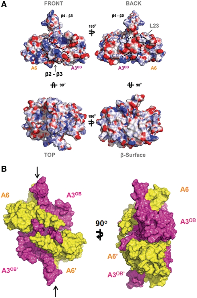
Characteristics of A3OB–A6 heterodimer and heterotetramer. (A) Surface charge distribution. Four views of the surface charge distribution of the A3OB–A6 heterodimer. The electrostatic potential surface of the A3OB and A6 dimer is calculated using APBS (71) and displayed as blue for a positively charged surface potential, red for negative and gray for neutral. The ‘front surface’ (upper left) is predominantly positively charged and the ‘back surface’ (upper right) predominantly negative. The ‘top’ view (lower left) shows pockets of positively charged surface areas next to the protruding β4–β5 hairpin. The ‘β-surface’ (lower right), formed mainly by the extended β-sheet of the dimer, contains large hydrophobic areas (gray). (B) The ‘shifted tetramer’ formed by two A3OB-A6 heterodimers in the crystal. The A3OB and A6 proteins in the complex are shown in surface mode, with the two A3OB chains in magenta and the two A6 domains in yellow. The β-surfaces of two A3OB–A6 heterodimers contact each other in the crystals. The ∼2000 Å2 total solvent accessible surface buried in this dimer–dimer interface is composed of ∼800 Å2 from A3OB–A3OB′ contacts, ∼600 Å2 contributed by A3OB–A6′, ∼600 Å2 by A3OB′–A6. The A6 and A6′ subunits do not interact, while A3OB interacts with three different OB-folds in this assembly. This (A3OB–A6)2 heterotetramer is distinct from canonical OB-fold homotetramers (78) in that the upper and lower dimer pseudo-dyads are not coinciding, but are shifted with respect to each other parallel to the interacting β-surface (See arrows representing pseudo-dyads in the upper and lower heterodimers).

