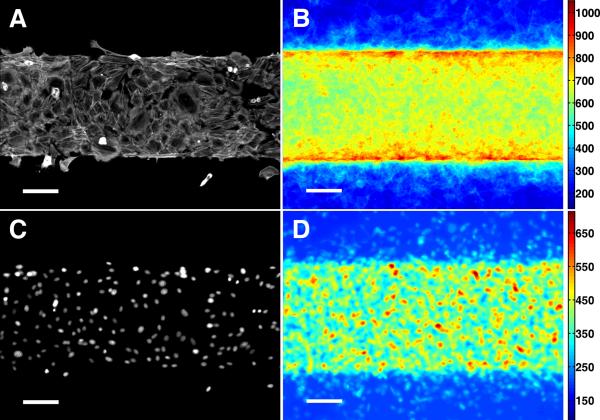
Figure 6. Stress fiber accumulation at FN/PEG interface.
Immunofluorescence microscopy of NMM-IIa in VMCs on FN/PEG substrate shown as (A) a single image and (B) stacked images (n = 45). Immunofluorescence microscopy of nuclei of VMCs on FN/PEG substrate shown as (C) a single image and (D) stacked images (n = 45). Scale bar, 100 μm.

