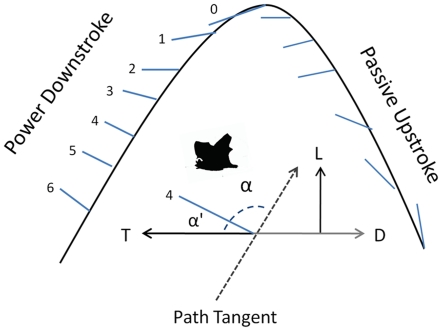
Figure 9. Angle of attack of the tail-membrane during fanning motion.
Graphic illustrating how the tail-membrane produces foreward thrust during a platform takeoff. The tip of the tail moves along a sinusoidal path through each stroke cycle represented by the curved black-line. Blue lines indicate the position of the tail-membrane relative to the sinusoidal path. The upstroke of the folded tail-membrane would likely be aerodynamically passive, whereas the downstroke provides a thrust force realtive to pitch angle and angle of attack. Numbers indicate tail-membrane position from top to bottom for a single downstroke. T = Thrust, L = Lift, D = Drag. Inset diagram illustrates how angle of attack and pitch angle were calculated for each tail-membrane position during the downstroke. A path tangent was drawn for each point position of the tail tip. α is the angle of attack of the tail-membrane relative to path (here illustrated for position 4 of the downstroke).

