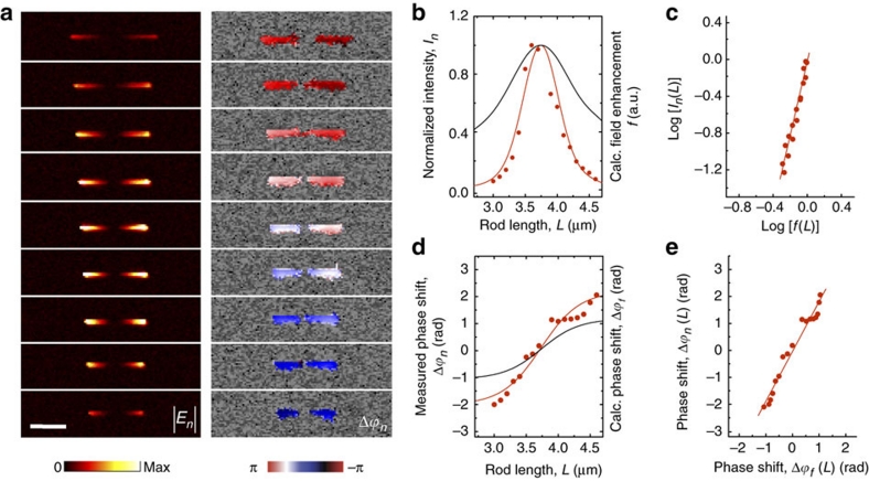
Figure 4. Verification of antenna-mediated elastic light scattering.
(a) Amplitude |En| and phase shift Δϕn maps of Au rods of different lengths. All the maps were recorded at an illumination wavelength of 11.1 μm. Demodulation was done with n=4. The scale bar denotes 2 μm. (b) Measured intensity In∝|En|2 (red symbols) and calculated field enhancement f (black solid line) at the hot spot (marked by a cross in Fig. 3b) as a function of the antenna length L. Both quantities are normalized to their maximum value. The red solid line shows the function f 4.08 (L). (c) Parametric representation of log[In(L)] and log[f(L)] (red symbols). A linear least-square fitting of the data points (red solid line) yields a slope of 4.08. (d) Measured phase shift Δϕn (red symbols) and calculated phase shift Δϕf (black solid line) at the hot spot (marked by a cross in Fig. 3b) as a function of antenna length L. The red solid line shows the function 1.85 Δϕf (L). (e) Parametric representation of Δϕn(L) and Δϕf(L) (red symbols). Linear least-square fitting of the data yields the relation Δϕn=1.85Δϕf.

