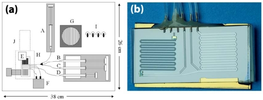
Figure 10.
(a) A schematic of the assembled bacterial detection system is shown. The system includes integrated syringe pumps (A-D), Moog micro valve (F), cooling fan (G), LED-based fluorescence excitation / detection system (H – dotted outline) with PMT detector (J), power toggle switches (I). The microfluidic purification/detection chip (E) is inserted into the unit directly above the thermoelectric heater cooler. The syringes are connected to the chip via TygonTM tubing (black lines) and contain the sample lysate (A), ethanol wash buffer (B), dH2O (C), and PCR master mix (D). The Moog micro valve (F) is also connected to the chip via tubing and controls pressurization and fluid flow through the chip outputs. The entire unit measures 36cm × 28cm × 15cm. Reprinted with permission [32], ©2003 Elsevier Science B.V.; (b) Photographic image of the microfluidic purification/detection chip (E).

