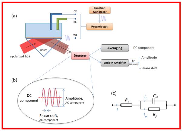
Figure 1.
(a) Schematic illustration of the setup. AC modulation from a function generator was applied to the Au sensor chip (WE) via a potentiostat. The DC component of the SPR response was obtained by directly averaging the SPR signal, and the AC component was converted to amplitude signal and phase shift signal by lock-in amplifier. (b) Illustration of DC component of SPR (averaged SPR signal), amplitude (peak-to-peak amplitude) and phase shift (relative to the applied potential) of AC component. (c) Randles equivalent circuit used to model both the conventional and plasmonic-based impedance spectra.

