
Figure 7.
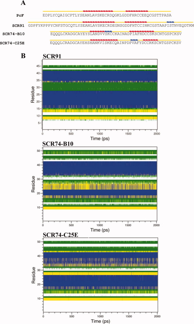
(A) Secondary structure-aided alignment of PcF, SCR91, SCR74-B10, and the SCR74-C25E mutant, performed by STRIDE program. Yellow line indicates a turn or a coil. Red line indicates an alpha-helix. Blue line indicates a 3–10 helix. (B) DSSP assignment of residues (mapped to the y-axis) during the evolution of a simulation (mapped to the x-axis) of SCR91, SCR74-B10, and SCR74-C25E. The different tertiary structure elements are color-coded as follows: coils in white, bends in green, turns in yellow, and alpha-helices in blue. [Color figure can be viewed in the online issue, which is available at wileyonlinelibrary.com.]