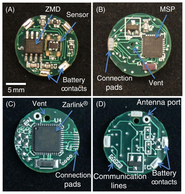
Fig. 1.
Photograph of circuit boards and main features for wireless Gen2 circuitry. The IMD side A (A) contains the piezoresistive pressure sensor, ZMD signal processor and battery contacts. IMD side B (B) contains the MSP430 microcontroller and eight connection pads for linking the IMD board to the RF board. RF side A (C) contains the Zarlink wireless chip and connection pads. RF side B (D) contains four communication lines for programming and calibration and battery contacts

